
Pneumatic slurry mixer

A mixer and slurry technology, which is applied to cement mixing devices, clay preparation devices, mixing operation control devices, etc., can solve the problems of easy sedimentation of cement slurry, pipe plugging, and no supporting mixing equipment for grouting equipment.

Pending Publication Date: 2020-10-23
河南省煤科院科明机电设备有限公司
View PDF0 Cites 0 Cited by
  • Summary
  • Abstract
  • Description
  • Claims
  • Application Information

AI Technical Summary

Problems solved by technology

The single-shaft stirring equipment does not stir evenly, the quality of the slurry cannot be guaranteed, and the stability is poor, and it is prone to tipping when used on slopes and other occasions
A pneumatic mixer with mixing equipment suitable for long-distance grouting in rail roadways, which mainly solves the problem of inconvenient installation of the mixer on site and the problem that the grouting equipment does not have matching mixing equipment
The double-shaft horizontal mixer mainly solves the problem of insufficient uniformity of single-shaft mixing, but it shares one inlet and outlet and is driven by dual motors, so it is not suitable for mine grouting operations.
The existing cement mixing equipment cannot meet the grouting operations in different application sites, and most of the work is done manually
At present, the cement mixer commonly used in coal mines has only one stirring shaft for stirring when mixing cement. When mixing cement, the cement slurry is very easy to precipitate and form agglomerates. When grouting, pipe blockage will occur, which is extremely The ground affects the operation efficiency of water blocking and filling grouting

Method used

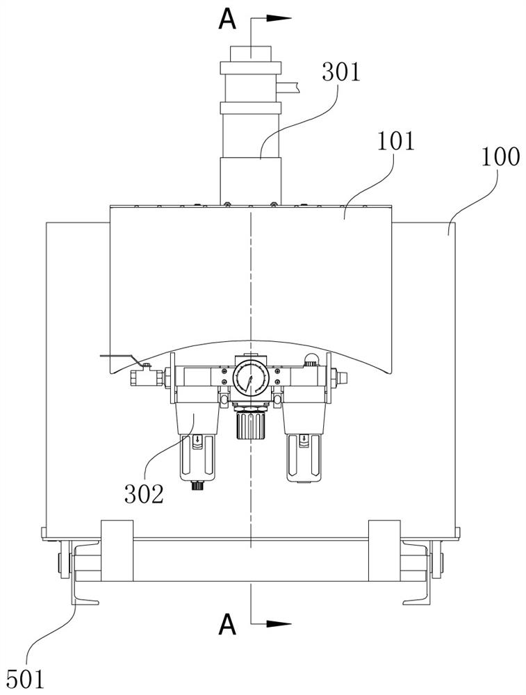
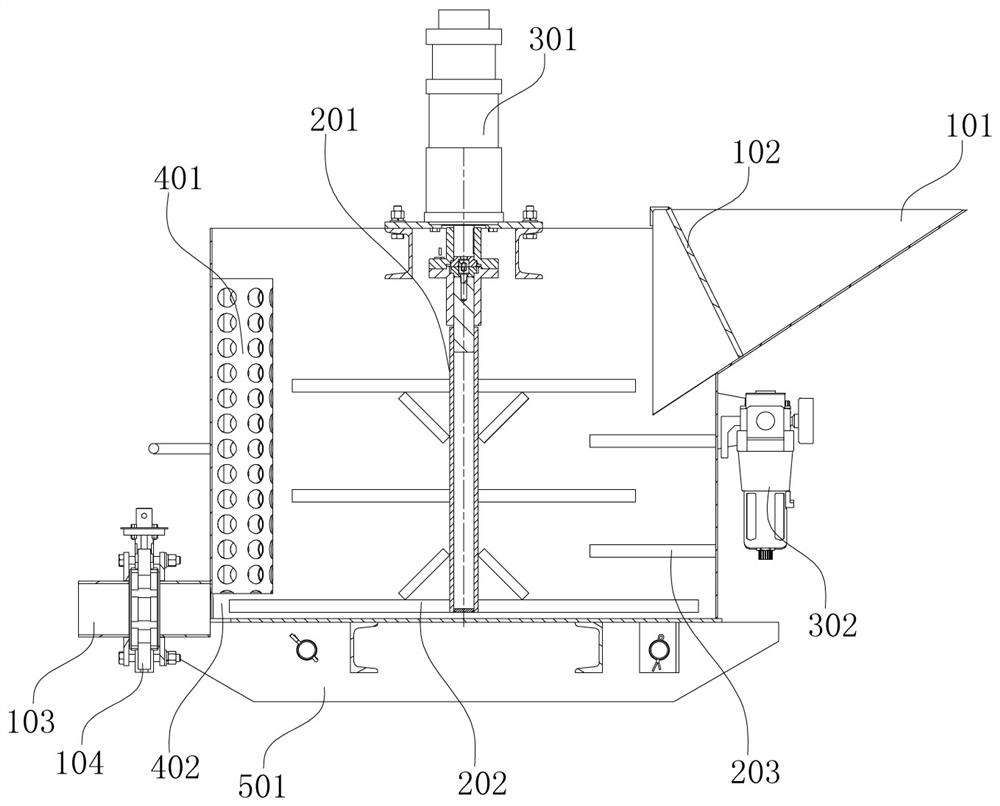
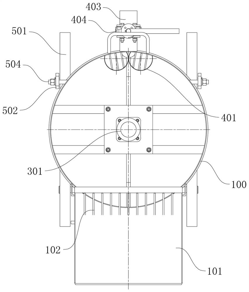

Image

  • Pneumatic slurry mixer
  • Pneumatic slurry mixer
  • Pneumatic slurry mixer

Examples


Embodiment Construction

[0046] The following will clearly and completely describe the exemplary schemes of the embodiments of the present invention with reference to the accompanying drawings of the specific embodiments of the present invention. Unless otherwise defined, the technical terms or scientific terms used in the present invention shall have the usual meanings understood by those skilled in the art.

[0047] It should be noted that when an element is "connected", "coupled" or "connected" to another element, it may mean that it is directly connected, coupled or connected, but it should be understood that there may be Intermediate elements; that is, positional relationships covering both direct and indirect connections.

[0048] It should be noted that the use of "a" or "a" and the like does not necessarily indicate a limitation of quantity. "Comprising" or "comprising" and similar words mean that the elements or items appearing before the word include the elements or items listed after the w...


PUM


Abstract

The invention belongs to the technical field of mine mixers. A pneumatic slurry mixer comprises a mixing cylinder, a mixing shaft, a driving portion, a feeding portion and a discharging portion, wherein the mixing shaft is arranged in the mixing cylinder, main mixing blades are arranged on the mixing shaft, multiple auxiliary mixing blades are arranged on the inner wall of the mixing cylinder, andthe main mixing blades and the auxiliary mixing blades are arranged in a staggered mode; the driving portion is used for driving the mixing shaft to act; the feeding portion is arranged on the upperportion of the mixing cylinder; and the discharging portion is arranged on the side portion of the mixing cylinder. According to the pneumatic slurry mixer, cement slurry does not precipitate in the long-term running process, the mixing effect is good, the slurry is easy to transfer, and the requirement for on-site grouting operation in a coal mine can be met; and meanwhile, the mixer can be usedon a flammable and explosive occasion, a strong magnetic occasion, a radiation occasion, a dusty occasion and other occasions, thereby being suitable for underground operation in the coal mine.

Description

technical field [0001] The invention belongs to the technical field of mine mixers, and in particular relates to a pneumatic slurry mixer. Background technique [0002] The mining activities in the coal mine factory area cause changes in the geological structure, resulting in subsidence, fracture, and looseness of the stratum, which greatly changes the groundwater system. In order to prevent the polluted groundwater from further infiltrating and spreading outwards, causing pollution to the surrounding areas, water blocking in the mine In grouting and grouting operations, according to different geological conditions and different application sites, it is necessary to use different grouting and grouting equipment to hydraulically inject the configured cementitious material slurry into the gaps and fractures in the aquifer and aquitard Broken zone, etc., and make it diffuse and consolidate, so as to block the water passage, fill the water-conducting gap, increase the geological...

Claims


Application Information

Patent Timeline
Patent Type & Authority Applications(China)
IPC IPC(8): B28C5/16B28C5/08B28C7/04B28C7/16
CPCB28C5/0806B28C5/16B28C7/04B28C7/163
Inventor 颜威合邓波张守金李博司琪蔡青峰孙庆润詹东阳路安林陈永生
Owner 河南省煤科院科明机电设备有限公司
Learn More