Protective sleeve for power cable through water

A technology for power cables and protective tubes, applied in the field of protective tube sleeves for power cables passing through water, can solve the problems of difficulty in checking the location of damaged points and difficult to find in time, so as to reduce the time-consuming maintenance, reduce the risk of failure, and prolong the cycle. Effect

Active Publication Date: 2021-08-27
YONGGAO CO LTD
View PDF12 Cites 0 Cited by
  • Summary
  • Abstract
  • Description
  • Claims
  • Application Information

AI Technical Summary

Problems solved by technology

[0004] The purpose of the present invention is to solve the shortcomings in the prior art that it is difficult for people to find out in time when the protective sleeve of a power cable is damaged, and it is difficult to check the position of the damaged point, and proposes a protective sleeve for a power cable through water

Method used


Image

  • Protective sleeve for power cable through water
  • Protective sleeve for power cable through water
  • Protective sleeve for power cable through water

Examples


Embodiment 1

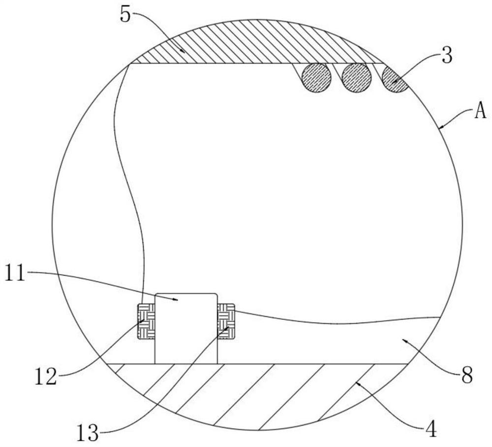
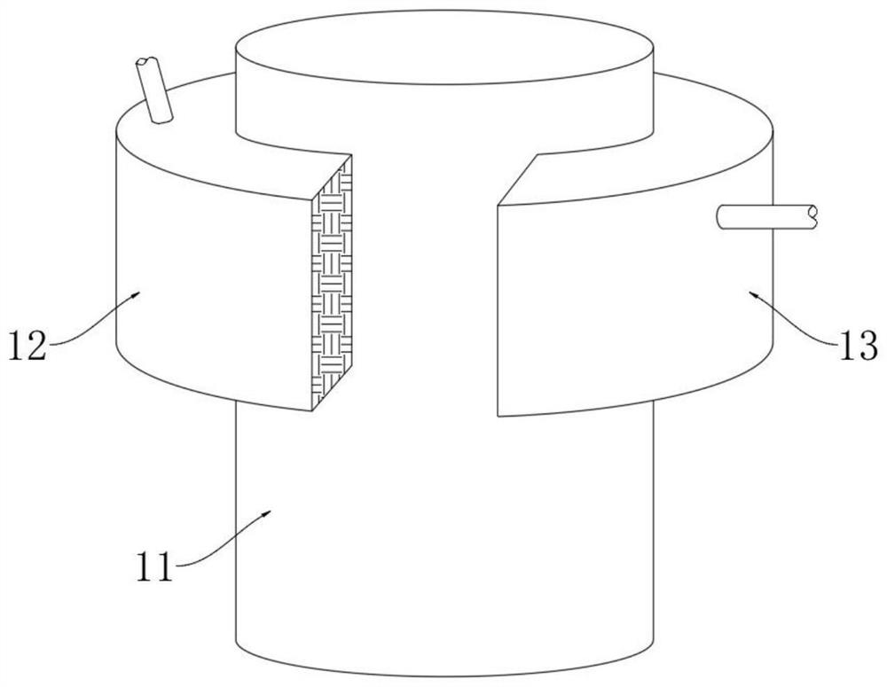
[0025] refer to Figure 1-5 , a kind of protective sleeve for power cables through water, comprising a protective tube 4, the protective tube 4 is covered with a visible layer 1, the visible layer 1 is made of a transparent elastic material, the visible layer 1 and the outer wall of the protective tube 4 There is a luminescent layer 2 between them, the luminescent layer 2 is electroluminescent paint, the protective tube 4 is provided with a wire core 6 with an insulating layer 5, an induction coil 7 is installed in the insulating layer 5, and the insulating layer 5 and the protective tube 4 A water-proof cavity 8 is formed between them, and a short-circuit device and a conduction device are fixedly arranged in the water-proof cavity 8, and a high-resistance ring 3 is set on the outer side of the insulating layer 5, and one end of the high-resistance ring 3 is electrically connected with the induction coil 7, and the high-resistance coil 3 is electrically connected to the induct...

Embodiment 2

[0036] refer to Figure 6 , the difference between this embodiment and Embodiment 1 is that: the outer fixed sleeve of the insulating layer 5 is provided with a friction sleeve 9, one end of the friction sleeve 9 is interference fit with a fixed ring 17, and the outer side of the friction sleeve 9 is wound with a A flexible spring 16, and one end of the flexible spring 16 is fixedly connected to the fixed ring 17, and the flexible spring 16 can only move away from the fixed ring 17 when stretched.

[0037]When the present embodiment is in use, the flexible spring 16 can be connected with the induction coil 7, and the flexible spring 16 is on a parallel branch, because the flexible spring 16 has an electrostrictive effect, so when an alternating current flows through the flexible spring 16, the flexible spring 16 The spring 16 will quickly expand and contract, thereby rubbing against the friction sleeve 9 to generate heat;

[0038] It is worth mentioning that when the flexible...


PUM


Abstract

The invention discloses a protective sleeve for a water-passing power cable, which comprises a protective tube, the protective tube is covered with a visible layer, and a luminescent layer is arranged between the visible layer and the outer wall of the protective tube. A wire core with an insulating layer is set inside the tube, an induction coil is installed in the insulating layer, and a water-proof cavity is formed between the insulating layer and the protective tube, and a short-circuit device and a conduction circuit are fixed in the water-proof cavity. The outer side of the insulating layer is covered with a high-resistance ring, one end of the high-resistance ring is electrically connected to the induction coil, and the other end of the high-resistance ring is electrically connected to the conduction device. The invention can help maintenance personnel judge whether the protective tube is damaged or not according to the luminescence of the luminescent layer, and the maintenance personnel do not need to use other maintenance tools for detection. It will emit light, so as to guide the maintenance personnel to quickly find the damaged point and reduce the time-consuming maintenance.

Description

technical field [0001] The invention relates to the technical field of power cable protection devices, in particular to a protection sleeve for a water-passing power cable. Background technique [0002] Power cables are often used in telecommunications or power transmission. In different occasions, protective sleeves with different functions are required to ensure the normal operation of the cables. For example, in an environment with complex lines and many electrical equipment, it is necessary to use flame-retardant and fire-resistant protective sleeves. ; On the road surface or in the pipeline, it is necessary to use wear-resistant and non-breakable protection sleeves; in the lake bottom, river bottom and other water-passing environments, it is necessary to use moisture-proof sealing protection sleeves. [0003] Most of the existing moisture-proof sealing protective sleeves realize the water-blocking function by adding a rigid armor layer and a protective layer to the outs...

Claims


Application Information

Patent Timeline
Patent Type & Authority Patents(China)
IPC IPC(8): H02G9/02G01R31/58
CPCG01R31/58H02G9/02
Inventor 林峰
Owner YONGGAO CO LTD
Why Eureka
Try Eureka