
Portable radiology department image reading device

A radiology, portable technology, applied in the field of portable radiology image reading devices, can solve the problems such as the height and angle of the light box cannot be adjusted, the local position of the X-ray film cannot be enlarged, and it is inconvenient.

Inactive Publication Date: 2020-10-20
桑胜
View PDF0 Cites 0 Cited by
  • Summary
  • Abstract
  • Description
  • Claims
  • Application Information

AI Technical Summary

Problems solved by technology

[0002] In the imaging diagnosis of the radiology department, patients are often diagnosed with the help of X-ray films made by X-ray equipment, so film reading plays an important role in the diagnosis of diseases and subsequent targeted treatment. The existing film reading device It uses a light box hanging on the wall as a light source, and then puts the image light film on the surface of the light box for reading, but the existing device cannot be moved, and medical personnel need to go to a designated place to read the film, which is very inconvenient, and the height of the light box , The angle cannot be adjusted, and it is inconvenient to use
At the same time, most of the existing X-ray films are directly stuck on the light box when viewing, which is very easy to drop
[0003] The existing radiology image reading device cannot zoom in on the local position on the X-ray film, which is inconvenient for doctors to inspect the local position. Due to the problem of light, it is inconvenient to clearly observe the black spots (lesions) on the X-ray film for monitoring , the use effect is poor, there is a possibility of misdiagnosis, and when encountering difficult and miscellaneous diseases that need to be discussed, it is inconvenient to zoom in and connect with external projection equipment. Therefore, we propose a portable radiology image reading device to solve the above problems

Method used


Image

  • Portable radiology department image reading device
  • Portable radiology department image reading device
  • Portable radiology department image reading device

Examples


Embodiment Construction

[0023] In order to make the object, technical solution and advantages of the present invention clearer, the present invention will be further described in detail below in combination with specific embodiments and with reference to the accompanying drawings. It should be understood that these descriptions are exemplary only, and are not intended to limit the scope of the present invention. Also, in the following description, descriptions of well-known structures and techniques are omitted to avoid unnecessarily obscuring the concept of the present invention.

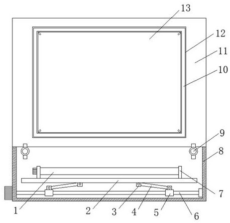
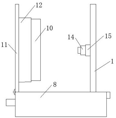
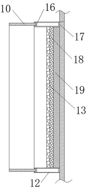
[0024] Such as Figure 1-4 As shown, a portable radiology image reading device proposed by the present invention includes a box body 8 and a box cover 11 connected to the upper end of the box body 8 through a 90° positioning spring hinge. The front surface of the box cover 11 is fixed with double The double-layer back-shaped plate 12, the double-layer back-shaped plate 12 is movably connected with the back-shaped telesco...


PUM


Abstract

The invention discloses a portable radiology department image reading device. The device comprises a box body and a box cover rotationally connected to the upper end of the box body through a 90-degree positioning spring hinge; a double-layer concentric-square-shaped plate is fixed to the front surface of the box cover. A concentric-square-shaped telescopic plate extending towards the front side is movably connected into the double-layer concentric-square-shaped plate. A storage battery fixed to the front surface of the box cover is arranged on the inner side of the double-layer concentric-square-shaped plate. An LED lamp panel fixed to the inner wall of the double-layer concentric-square-shaped plate is arranged on the front side of the storage battery. A transparent white board fixed tothe inner wall of the double-layer concentric-square-shaped board is arranged on the front side of the LED lamp board. A transverse bidirectional threaded rod is rotatably connected to the inner wallof the box body, two moving blocks are connected to the bidirectional threaded rod through threads, a supporting plate located on the upper side of the bidirectional threaded rod is arranged in the box body, and two pairs of lug plates are fixed to the lower surface of the supporting plate. According to the portable radiology department image reading device, the diseased region of a patient can beobserved conveniently, the diagnosis precision is improved, X-ray films can be shot and projected conveniently, joint discussion is facilitated, and carrying is extremely convenient.

Description

technical field [0001] The invention relates to the field of radiology diagnostic equipment, in particular to a portable radiology image reading device. Background technique [0002] In the imaging diagnosis of the radiology department, patients are often diagnosed with the help of X-ray films made by X-ray equipment, so film reading plays an important role in the diagnosis of diseases and subsequent targeted treatment. The existing film reading device It uses a light box hanging on the wall as a light source, and then puts the image light film on the surface of the light box for reading, but the existing device cannot be moved, and medical personnel need to go to a designated place to read the film, which is very inconvenient, and the height of the light box , The angle cannot be adjusted, and it is inconvenient to use. At the same time, most of the existing X-ray films are directly stuck on the light box when viewed, which is very easy to drop. [0003] The existing radi...

Claims


Application Information

Patent Timeline
IPC IPC(8): G02B27/02
CPCG02B27/024G02B27/028
Inventor 桑胜宋洛伟刘志伟
Owner 桑胜
Learn More