Two-stage compression sliding vane vacuum pump driven by rotary ring

A two-stage compression, sliding vane technology for use in rotary piston/oscillating piston pump components, rotary piston/oscillating piston pump combinations for elastic fluids, and components for pumping devices for elastic fluids It can solve problems such as unfavorableness, small change of shape line vector diameter, and increase of internal volume ratio.

Pending Publication Date: 2020-10-20
CHINA UNIV OF PETROLEUM (EAST CHINA)
View PDF0 Cites 0 Cited by
  • Summary
  • Abstract
  • Description
  • Claims
  • Application Information

AI Technical Summary

Problems solved by technology

[0003] With the increase of the application area of ​​the vacuum pump, the requirements for the vacuum degree of the vacuum pump are also increasing. The concentric double-wave ring multi-sliding vane rotor machine proposed in the patent with the publication number CN277724 adopts the cavity profile constructed by the cosine function curve. The swivel divides the inner and outer cavity to realize a two-stage structure, which increases the flow rate of the liquid that can be transported and improves the stress of the slide; however, the change in the shape line vector is small, which is not conducive to increasing the internal volume ratio; the transmission disc There is relative movement between the cover and the cover, increasing the leakage

Method used


Image

  • Two-stage compression sliding vane vacuum pump driven by rotary ring
  • Two-stage compression sliding vane vacuum pump driven by rotary ring
  • Two-stage compression sliding vane vacuum pump driven by rotary ring

Examples


Embodiment Construction

[0043] The present invention will be further described below in conjunction with accompanying drawing.

[0044] like figure 1 As shown, it is a three-dimensional assembly diagram of a two-stage compression vane vacuum pump driven by a swivel, including: front end cover (1), swivel cover (2), swivel (3), sliding vane (4), Cylinder (5) and rear end cover (6).

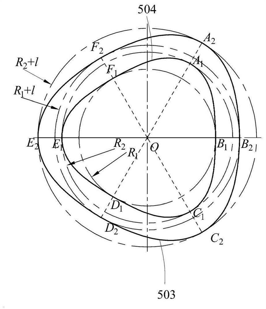
[0045] like figure 2 As shown, it is an inner chamber profile diagram of a two-stage compression vane vacuum pump driven by a swivel, and the contour profile diagram of the cylinder (5) is formed in the following way: the center of rotation of the cylinder (5) is the coordinate origin O Set up the polar coordinate system, the equation of the inner cylinder profile (504) is:

[0046]

[0047] The equation of the outer cylinder profile (503) is:

[0048]

[0049] Among them, ρ—the vector diameter of the cylinder profile, mm;

[0050] R 1 —The radius of the inscribed circle of the molded line inside the cylinder...


PUM


Abstract

The invention discloses a two-stage compression sliding vane vacuum pump driven by a rotary ring. The vacuum pump is composed of a front end cover (1), a rotary ring cover (2), a rotary ring (3), slide vanes (4), a cylinder (5) and a rear end cover (6), wherein the outer cylinder shape line (503) and the inner cylinder shape line (504) are all smooth, and the radius of curvature is continuous; thefront end cover (1), the rotary ring cover (2), the rotary ring (3) and the cylinder (5) form six cavity bodies with different volumes, the volume of the three cavities on the outer side of the rotary ring (3) is the same, and the volume of the three cavities on the inner side of the rotary ring (3) is the same. According to the vacuum pump, the exhaust amount can be increased, the inner volume ratio is improved, the clearance volume is reduced, the volume utilization rate and the vacuum degree of the vacuum pump are improved, and the stress condition of the sliding vanes is improved.

Description

technical field [0001] The invention belongs to the field of vacuum pumps, in particular to a two-stage compression vane type vacuum pump driven by a rotary ring. Background technique [0002] The sliding vane vacuum pump is a volumetric fluid machine, relying on the continuous operation of the sliding vane in the pump chamber, the gas is sucked in and compressed by the suction port, and finally discharged from the exhaust port; Its advantages are widely used in metallurgy, electronics, medicine, and automobile industries; its key technology is the inner cavity shape of the pump cavity, and the shape of the inner cavity of the pump cavity directly affects the working performance of the vacuum pump. The common working cavity of the sliding vane vacuum pump is single cavity or double cavity. This kind of sliding vane vacuum pump has relatively small displacement and internal volume, and the ultimate vacuum degree of the vacuum pump is low. [0003] With the increase of the ap...

Claims


Application Information

Patent Timeline
Patent Type & Authority Applications(China)
IPC IPC(8): F04C25/02F04C23/00F04C29/12F04C29/00
CPCF04C23/001F04C25/02F04C29/00F04C29/12F04C2240/10
Inventor 王君刘译阳董丽宁谈庆朋武萌奚周瑾
Owner CHINA UNIV OF PETROLEUM (EAST CHINA)
Why Eureka
Try Eureka