
Brake actuator

A technology of actuators and brake cylinders, applied in the field of parking brake or emergency braking system, to reduce maintenance, improve flexibility and long-term, and facilitate maintenance

Active Publication Date: 2020-10-16
FAIVELEY TRANSPORT NORDIC AB
View PDF8 Cites 0 Cited by
  • Summary
  • Abstract
  • Description
  • Claims
  • Application Information

AI Technical Summary

Problems solved by technology

Although these known systems represent well-functioning designs, there is still room for improvement

Method used


Image

  • Brake actuator
  • Brake actuator
  • Brake actuator

Examples


Embodiment Construction

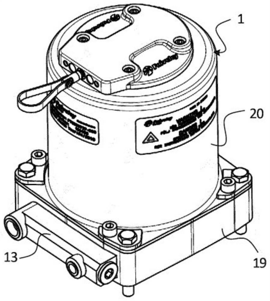
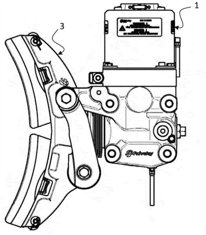
[0035] refer to figure 1 and 2 , describes a possible embodiment of a brake actuator 1 for activating the actuating capability of the brake 3 , which is adapted to act on the brake cylinder 2 . The utility model relates to a braking actuator of a railway vehicle braking system.

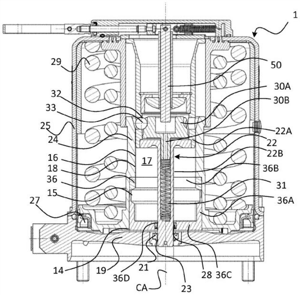
[0036] will now refer to image 3 Describing generally the brake actuator 1 and its features, the actuator 1 comprises a housing or body 20 having a base member 19 and a cylindrical portion 25 . The base member 19 has an opening 21 relative to the brake cylinder 2 . The opening 21 is a circular opening which slidingly receives a thrust member in the shape of a sleeve 22 which is fitted in the opening 21 in a sealing manner by means of sealing means 23 , for example an O-ring.

[0037] Furthermore, the brake actuator 1 comprises a piston 24 mounted in a cylindrical portion 25 of the main body 20 and together with the main body 20 defines a Figure 4 Pressure chamber 26 is shown. Pressurized fluid...


PUM


Abstract

A brake actuator for a railway vehicle brake system has a thrust sleeve (22) configured to provide braking force to the brake system, and a slide (30A) axially moveable in the thrust sleeve (22) between a release position and a locking position. The actuator (1) further has a piston (24) biased by spring means (29) and linked to an anchoring member (36). A plurality of balls (33) are disposed in respective openings (32) of the sleeve (22) between the slide (30) and the anchoring member (36). In the locking position, the balls (33) are configured to move under the action of a profiled surface of the slide (30A) to axially couple the anchoring member (36) with the sleeve (22). In the release position, the balls (33) are configured to axially uncouple the anchoring member (36) from the sleeve(22). The profiled slide surface has a locking groove configured to engagingly receive the balls (33) when the slide (30A) is in the locking position.

Description

technical field [0001] The present invention relates to braking of railway vehicles, and in particular to a parking brake or emergency braking system comprising a brake actuator acting on a brake cylinder included in the brakes of a railway vehicle. Background technique [0002] Railway vehicles are usually equipped with a brake system having a piston movable under pneumatic action which causes the braking action of the vehicle's wheels. [0003] Typically, systems such as shutdown or emergency situations are used with reactors whose purpose is not to vary with the pressure of the pressurized fluid. In such brake actuators, the braking force is provided by a spring, and the braking effect is applied in response to pressure in the absence of pressurized fluid. Once the brake actuator is actuated, the actuator stops until pressure in the actuator is restored. [0004] A road vehicle marking braking system reflecting the above background art is known from WO2008 / 085128A1. An...

Claims


Application Information

Patent Timeline
Patent Type & Authority Applications(China)
IPC IPC(8): B60T17/08
CPCB60T17/083B60T17/086F16D65/28F16D2121/02F16D2123/00
Inventor T·佩尔松G·雷恩伯格
Owner FAIVELEY TRANSPORT NORDIC AB
Learn More