X-ray optical framing imaging system

A framing imaging and X-ray technology, used in X-ray energy spectrum distribution measurement, X/γ/cosmic radiation measurement, scientific instruments, etc., can solve problems such as interference, different application scenarios, and difficulty in further improvement. , to achieve the effect of adjustable temporal resolution, high spatial resolution, and ingenious design

Active Publication Date: 2020-10-16
LASER FUSION RES CENT CHINA ACAD OF ENG PHYSICS
View PDF12 Cites 2 Cited by
  • Summary
  • Abstract
  • Description
  • Claims
  • Application Information

AI Technical Summary

Problems solved by technology

[0003] However, the time resolution of CCD and CMOS currently used for ultra-fast two-dimensional imaging cannot meet the needs, the highest can only reach 100ns level, and the corresponding readout speed is only 10 7 / s frame rate
Although X-ray framing cameras and streak cameras have been widely used in the diagnosis of ultrafast physical processes, the application scenarios are not exactly the same
The framing camera based on photoelectric conversion is limited by the space charge and the processing technology of the micro-channel plate, and the time-space resolution (time resolution 30ps, space resolution 30um) is difficult to be further improved; and it is extremely vulnerable to strong neutrons, gamma rays, and electromagnetic noise Waiting for interference
[0004] Therefore, the existing imaging equipment can no longer show the ultrafast process of two-dimensional space evolution over time on a finer scale, and there is an urgent need to develop new optical ultrafast diagnostic technologies

Method used


Image

  • X-ray optical framing imaging system

Examples


Embodiment Construction

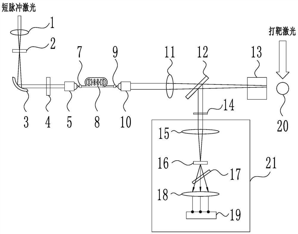
[0025] The present invention will be further described below in conjunction with embodiment and accompanying drawing.

[0026] Such as figure 1 As shown, an X-ray optical framing imaging system mainly includes a supercontinuum generation module, a supercontinuum broadening module, a probe photoaction module and an optical framing recording module, wherein the supercontinuum generation module can convert the incident The short-pulse laser light of the supercontinuum is converted into supercontinuum probe light, and the supercontinuum broadening module can convert the supercontinuum probe light injected from the supercontinuum generation module into chirped pulse probe light, and the probe light action module can Make the chirped pulse probe light injected from the supercontinuum broadening module carry the time-space evolution process information of the X-rays generated by the interaction between the targeting laser and the target 20, and the optical framing recording module ca...


PUM


Abstract

The invention discloses an X-ray optical framing imaging system that comprises a super-continuum spectrum generation module, a super-continuum spectrum broadening module, a probe light action module and an optical framing recording module, wherein the super-continuum spectrum generation module can convert short-pulse laser into super-continuum spectrum probe light; the super-continuum spectrum broadening module can convert the super-continuum spectrum probe light into chirped pulse probe light; the probe light action module can enable chirped pulse probe light to carry space-time evolution process information of X-rays generated by interaction of targeting laser and a target material, and the optical framing recording module can spatially divide one beam of chirped pulse probe light into aplurality of beams and record the beams of chirped pulse probe light as a plurality of two-dimensional images with time intervals. By adopting the technical scheme, the invention can be used for measuring the X-ray space-time evolution process under the conditions of an extremely small space and an extremely short time scale, and serves the research of a high-energy density related physical process.

Description

technical field [0001] The invention relates to the technical field of ultrafast process diagnosis, in particular to an X-ray optical framing imaging system. Background technique [0002] In the research of laser inertial confinement fusion, many physical processes that people care about happen extremely fast and the space scale is extremely small, especially the spatiotemporal evolution process of X-rays. This requires the detection technology to have extremely high temporal and spatial resolution capabilities. [0003] However, the time resolution of CCD and CMOS currently used for ultra-fast two-dimensional imaging cannot meet the needs, the highest can only reach 100ns level, and the corresponding readout speed is only 10 7 / s frame rate. Although X-ray framing cameras and streak cameras have been widely used in the diagnosis of ultrafast physical processes, their application scenarios are not exactly the same. The framing camera based on photoelectric conversion is l...

Claims


Application Information

Patent Timeline
Patent Type & Authority Applications(China)
IPC IPC(8): G01T1/15G01T1/24G01T1/36
CPCG01T1/15G01T1/244G01T1/366
Inventor 刘祥明王峰彭晓世徐涛理玉龙魏惠月关赞洋刘永刚刘欣城任宽
Owner LASER FUSION RES CENT CHINA ACAD OF ENG PHYSICS
Why Eureka
Try Eureka