
Optical storage and charging microgrid system and control method thereof

A technology of energy storage control and photovoltaic controller, which is applied in the direction of power network operating system integration, information technology support system, charging station, etc. Loss increase and other issues, to achieve the effect of seamless switching between off-grid and off-grid, guarantee the quality of power supply of the system, and reduce energy loss

Pending Publication Date: 2020-10-16
SHENZHEN KSTAR NEW ENERGY CO LTD
View PDF7 Cites 6 Cited by
  • Summary
  • Abstract
  • Description
  • Claims
  • Application Information

AI Technical Summary

Problems solved by technology

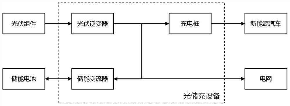
[0004] (1) Photovoltaic power generation equipment uses traditional photovoltaic inverters to form a network from the AC side. When the system load (that is, the charging pile) is less than the power of photovoltaic power generation, the remaining energy needs to be charged to the energy storage battery system through the energy storage converter, so that There are two defects: A. The photovoltaic energy charging circuit needs to pass through photovoltaic grid-connected inverters and energy storage bidirectional converters, and the additional energy loss increases by more than 2%.
This solution also has two defects: A. One more stage of AC to DC conversion, the additional energy loss increases by more than 1%; B. When the power grid fails, even if the battery power is sufficient, the charging pile is still unusable, resulting in economic losses
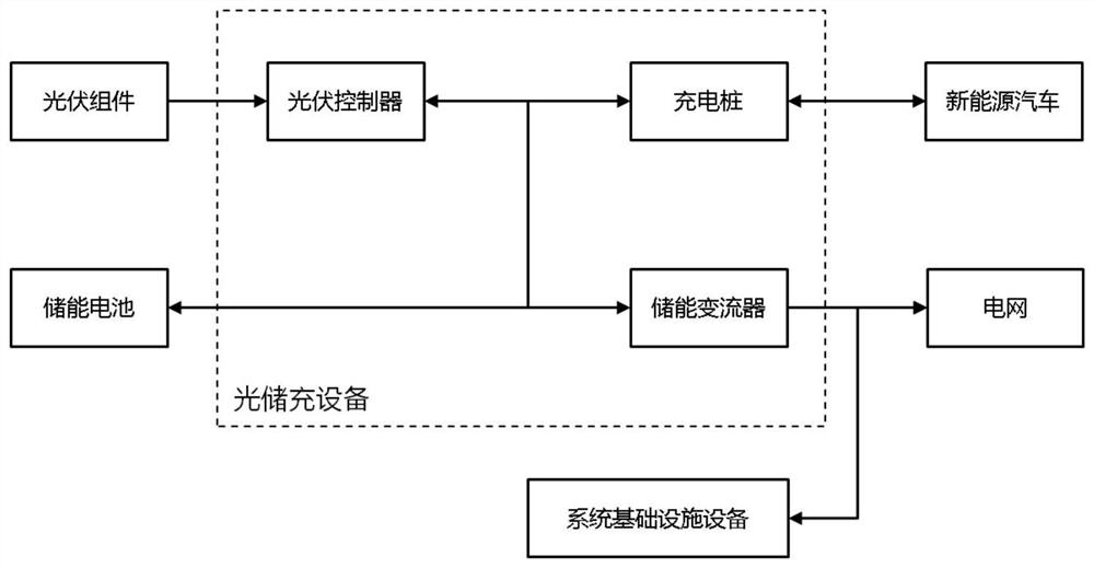
However, this solution has very serious application problems: it only considers the main energy conversion equipment such as photovoltaic charging controllers, charging piles, and bidirectional energy storage converters, and does not consider the basics of air conditioning, refrigeration, lighting, and monitoring that support the normal operation of the energy storage system. The power consumption of facilities and equipment, and the infrastructure equipment is the premise to ensure the normal operation of the main equipment of the system. Basically, this part of the equipment needs to use AC power supply
The current practice is to draw electricity from the public grid (such as image 3 As shown), there are two defects in this scheme, which make the demonstration project unable to be promoted commercially:
[0007] (1) When the power grid fails or fluctuates abnormally, even if the photovoltaic and charging piles can be used, because the power supply of infrastructure equipment cannot be guaranteed, the solar storage and charging system is still unavailable
[0008] (2) When the energy storage battery is fully charged, on the one hand, in order to prevent the energy storage battery from overcharging and limit photovoltaic power generation; on the other hand, it still draws power from the grid to supply power for infrastructure equipment, resulting in energy waste and affecting the economy

Method used


Image

  • Optical storage and charging microgrid system and control method thereof
  • Optical storage and charging microgrid system and control method thereof
  • Optical storage and charging microgrid system and control method thereof

Examples


Embodiment Construction

[0055] The preferred embodiments of the present invention will be further described in detail below.

[0056] Such as Figure 4 As shown, a light-storage charging micro-grid system, which includes a photovoltaic power generation unit, an energy storage unit, a photovoltaic controller, an energy storage converter, and an off-grid switching unit. The photovoltaic power generation unit is connected to the DC bus through the photovoltaic The energy storage battery and the energy storage converter are respectively connected to the DC bus, and the charging pile is directly hung on the DC bus to form a DC network; the energy storage converter is connected to the power grid and load connection; the photovoltaic controller is used to control the photovoltaic power generation unit to charge the energy storage unit; the grid-connected and off-grid switching unit is used to switch the energy storage converter between grid-connected and off-grid. First, the system power supply and load eq...


PUM


Abstract

The invention provides an optical storage and charging microgrid system and a control method thereof. The optical storage and charging microgrid system comprises a photovoltaic power generation unit,an energy storage unit, a photovoltaic controller, an energy storage converter and a grid-connected and off-grid switching unit, the photovoltaic power generation unit is connected with a direct current bus through the photovoltaic controller, an energy storage battery and the energy storage converter are connected with the direct current bus, and a charging pile is directly hung on the direct current bus to form a direct current network; wherein the energy storage converter is connected with a power grid and a load through the grid-connected and off-grid switching unit to form an alternatingcurrent network; the photovoltaic controller is used for controlling the photovoltaic power generation unit to charge the energy storage unit; and the grid-connected and off-grid switching unit is used for realizing grid-connected and off-grid state switching of the energy storage converter. By adopting the technical scheme of the invention, the energy loss is reduced, the economy is improved, thegrid-connected and off-grid seamless switching is realized, and the power supply quality of the system is ensured; and when the power grid is powered off or abnormally fluctuates, off-grid operationcan be fully automatically realized, and uninterrupted development of optical storage and charging services is ensured.

Description

technical field [0001] The invention belongs to the field of new energy and power electronics, and in particular relates to an optical storage charging micro-grid system and a control method thereof. Background technique [0002] In the context of the current general trend of vehicle electrification, charging piles, as supporting facilities for new energy vehicles, are in strong demand. However, in the design and construction process of various charging stations, the power distribution capacity often becomes the bottleneck of the power station scale, and even the charging business cannot be carried out due to the limited power distribution. Fortunately, due to the rapid decline in the cost of photovoltaic power generation and lithium battery energy storage and the development of control technology, the comprehensive application of photovoltaic storage and charging is possible and economical. The photovoltaic power generation subsystem can solve the problem of limited power ...

Claims


Application Information

Patent Timeline
IPC IPC(8): B60L53/51B60L53/53B60L53/64H02J7/02H02J9/06
CPCB60L53/51B60L53/53B60L53/64H02J7/02H02J9/062Y04S20/20Y02B70/30Y02T10/70Y02T10/7072Y02T90/12
Inventor 何少强廖琛琛刘程宇
Owner SHENZHEN KSTAR NEW ENERGY CO LTD
Learn More