
Resistance spot welding method and method of manufacturing welded parts

A technology of resistance spot welding and welding conditions, applied in resistance welding equipment, manufacturing tools, welding equipment, etc., can solve the problem of inability to ensure the diameter of the nugget, and achieve the effect of improving work efficiency

Active Publication Date: 2022-03-08
JFE STEEL CORP
View PDF12 Cites 0 Cited by
  • Summary
  • Abstract
  • Description
  • Claims
  • Application Information

AI Technical Summary

Problems solved by technology

[0023] However, in the technologies described in Patent Documents 1 and 2, there is a problem in that appropriate welding conditions are considered to be changed depending on the presence or absence and magnitude of the disturbance, so that it is impossible to prevent the dispersion from occurring when more than expected plate gaps and shunts occur. Ensure the desired nugget diameter under the conditions

Method used


Image

  • Resistance spot welding method and method of manufacturing welded parts
  • Resistance spot welding method and method of manufacturing welded parts
  • Resistance spot welding method and method of manufacturing welded parts

Examples


Embodiment

[0126] For the plate group of 2 or 3 overlapping metal plates shown in Table 1, test welding is carried out under the conditions shown in Table 1, and then, for the 2 or 3 overlapping metal plates shown in Table 2 The plate group of plates was subjected to main welding under the conditions shown in Table 2 to produce welded joints (welded parts).

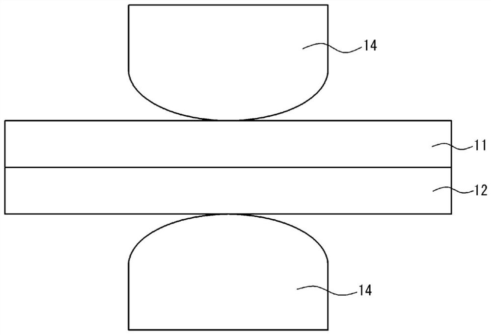
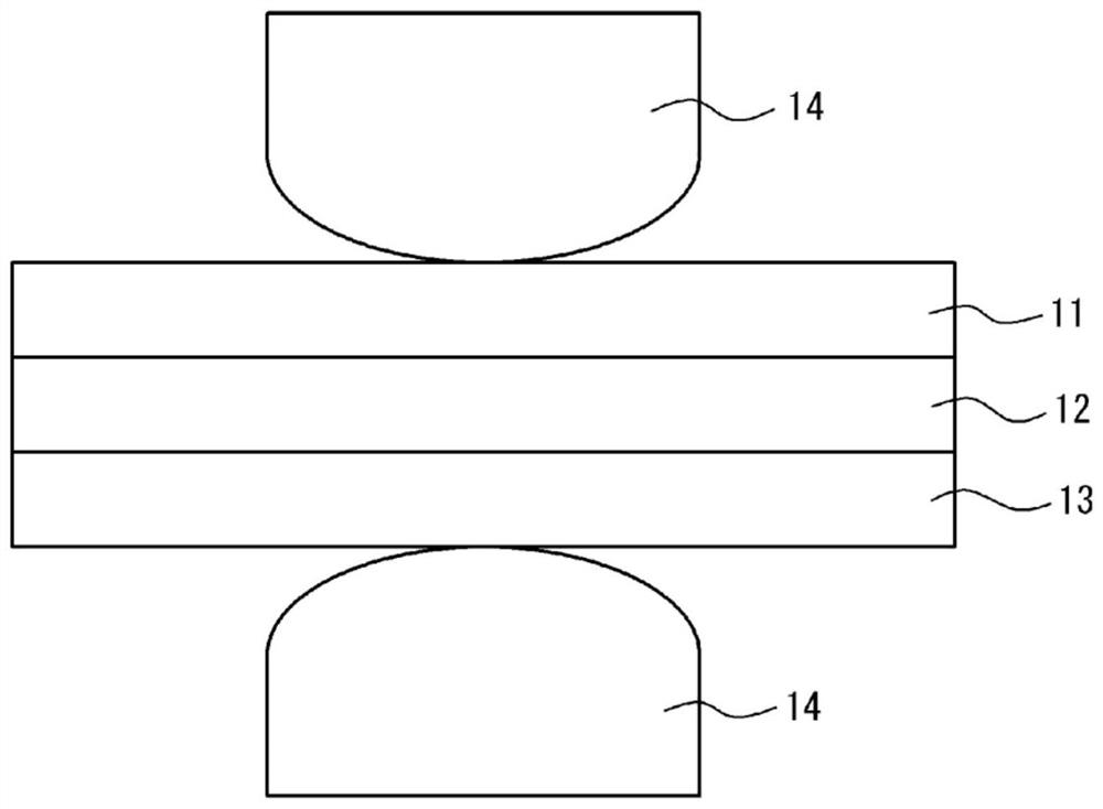
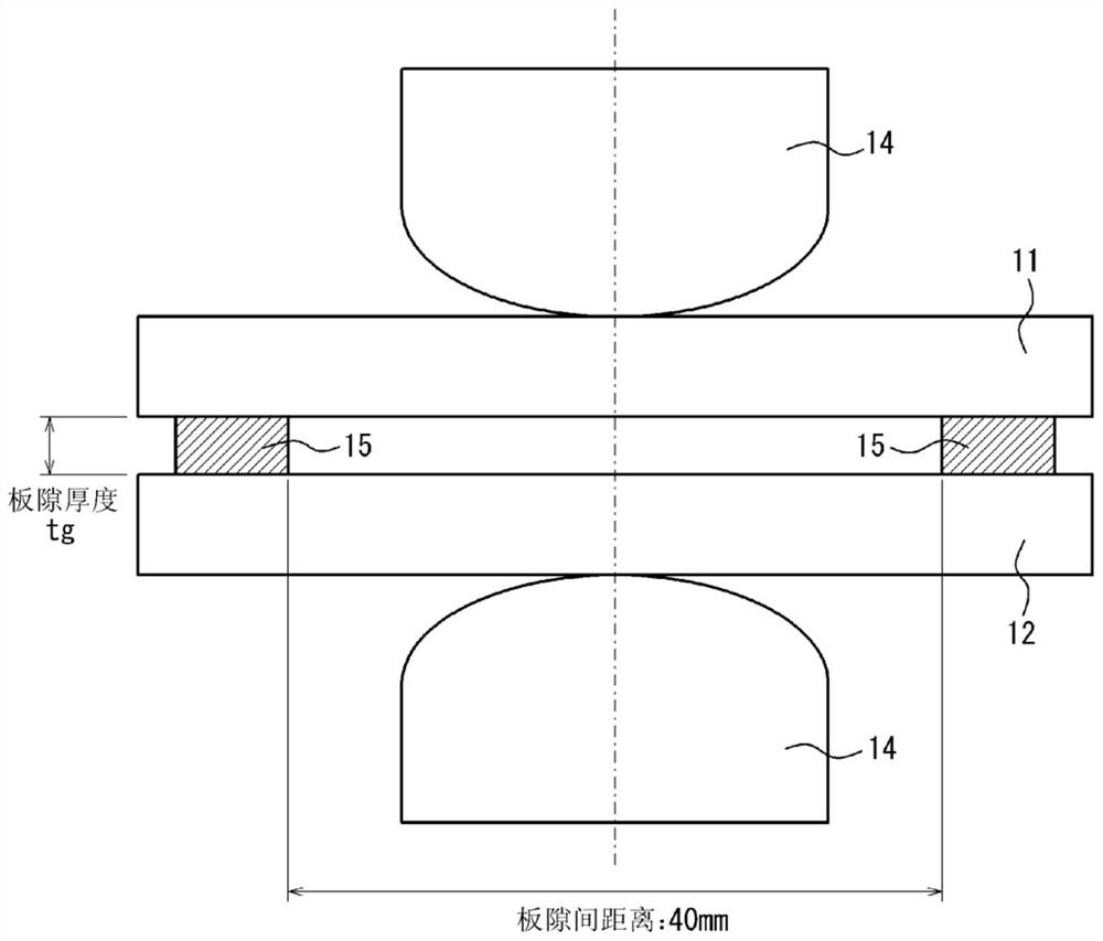
[0127] Here, trial soldering and main soldering are performed in such figure 1 and figure 2 The unperturbed state is shown as well as Figure 3-6 The simulations shown were performed under the disturbed state. In the figure, symbols 11, 12 and 13 are metal plates, 14 is an electrode, 15 is a spacer, and 16 is a welded point. It should be stated that in image 3 and Figure 4 Among them, spacers 15 are inserted between the metal plates 11-12 and between the metal plates 12-13, and clamped from above and below (not shown), thereby providing gaps having various gap thicknesses tg. It should be noted that the board gap distances ...


PUM


Abstract

The main welding and the trial welding before the main welding are performed, and the trial welding is performed under two or more welding conditions. During the trial welding, the pressurization of the material to be welded before the start of energization is stored for each welding condition to reach the setting In addition, in the above-mentioned main welding, pressurization of the material to be welded is carried out under the same conditions as the above-mentioned trial welding before the start of energization. According to each welding condition, the pressurized pressure parameter at the time is compared with the parameters stored in the above test welding, so as to set the time change curve of the instantaneous calorific value of the main welding and the target value of the cumulative calorific value, and control according to the target value Adaptive control welding of energized amount.

Description

technical field [0001] The present invention relates to a resistance spot welding method aimed at stably securing a nugget diameter without causing dispersion, especially when the influence of a disturbance such as a shunt or a plate gap is large. Background technique [0002] In general, the resistance spot welding method, which is one of lap resistance welding methods, is used to join overlapping steel plates. [0003] In this welding method, two or more overlapping steel plates are clamped and pressed from above and below with a pair of electrodes, and a high-current welding current is energized between the upper and lower electrodes for a short time to join. The resistance heat generated by the high-current welding current produces spot-like welded parts. This point-shaped welded portion is called a nugget, and is a portion where both steel plates melt and solidify at the contact position of the steel plates when current is passed through the stacked steel plates. Thro...

Claims


Application Information

Patent Timeline
Patent Type & Authority Patents(China)
IPC IPC(8): B23K11/11B23K11/24
CPCB23K11/11B23K11/24B23K11/115B23K11/255B23K11/257
Inventor 泽西央海松田广志池田伦正
Owner JFE STEEL CORP
Learn More