Winding battery cell, battery and battery module structure
A battery cell and winding core technology, which is applied to battery pack parts, secondary batteries, structural parts, etc., can solve problems such as lithium deposition and powder drop at corners, so as to prevent lithium deposition, prolong service life, and improve safety performance Effect
- Summary
- Abstract
- Description
- Claims
- Application Information
AI Technical Summary
Problems solved by technology
Method used
Image
Examples
Embodiment approach 1
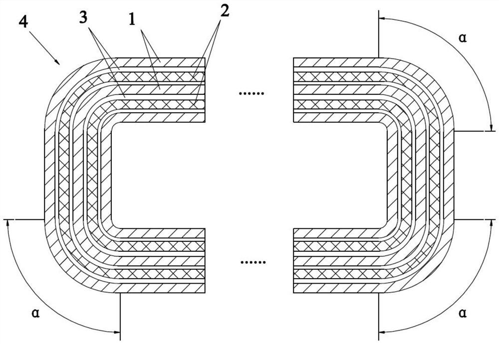
[0030] A winding cell, comprising a positive electrode sheet 1, a negative electrode sheet 2, and a separator 3 arranged between the positive electrode sheet 1 and the negative electrode sheet 2, and the positive electrode sheet 1, the separator 3, and the negative electrode sheet 2 are wound to form a roll of a hollow structure Core 4, the radian at the corner of winding core 4 is α, 0°figure 1 As shown, the corner can be understood as the angle formed between the pole piece in the horizontal direction of the winding core 4 and the pole piece in the longitudinal direction of the winding core 4 during the winding process of the positive electrode sheet 1, the separator 3 and the negative electrode sheet 2 around the winding needle. There is a smooth transition between the pole pieces in the transverse direction of the core 4 and the pole pieces in the longitudinal direction of the winding core 4 . Because the existing cell winding structure will flatten the wound electrode when...
Embodiment approach 2
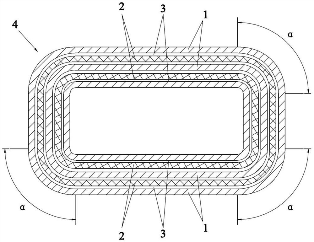
[0037] The difference from Embodiment 1 is that: the radian α at the corner of this embodiment is 90°≤α≤120°, the arc edge at the corner of the winding core 4 is an elliptical arc, and the corner of the winding core 4 is a square edge. The number of corners of the winding core 4 is limited to the maximum value to prevent the number of corners of the winding core 4 from being too large, resulting in an increase in production costs, and at the same time it is difficult to match the corresponding housing 5, increasing the difficulty of production; further limiting the radian of the corners of the winding core 4 The range of α satisfies the need to increase the radius of curvature of the positive electrode sheet 1, the separator 3 and the negative electrode sheet 2 during winding, and avoid the 180° corner position of the winding core 4, thereby avoiding the 180° bending of the electrode sheet , to improve the phenomenon of decarburization and powder loss or copper leakage caused b...
Embodiment approach 3
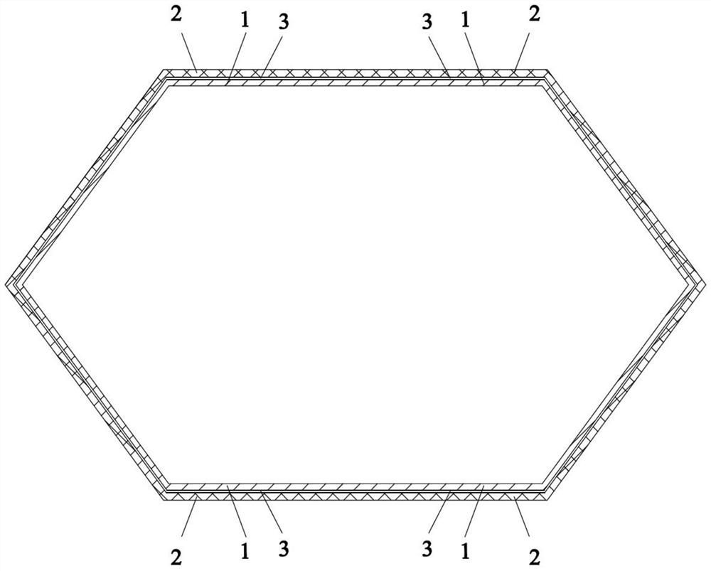
[0040] The difference from Embodiment 1 is that the number of corners of the winding core 4 in this embodiment is 6, and the cross-sectional shape of the hollow structure is ellipse. Such as image 3 As shown, the number of corners of the winding core 4 is limited to an intermediate value, so as to avoid the situation that the corner position of the winding core 4 will appear at 180°, thereby avoiding the 180° bending of the pole piece, and at the same time reducing the difficulty of the production process of the winding core 4 , helps to reduce the production cost of the battery; according to the shape of the combined battery 6, the hollow structure can be designed into an ellipse, which is convenient for placing the elliptical combined battery 6 or battery pack in the hollow structure, which helps to increase the capacity of the battery. In addition, it can also match the internal structure of the car, which helps to improve the flexibility and energy density of the battery ...
PUM
 Abstract
Description
Claims
Application Information
 - Generate Ideas
- Intellectual Property
- Life Sciences
- Materials
- Tech Scout
- Unparalleled Data Quality
- Higher Quality Content
- 60% Fewer Hallucinations
Browse by: Latest US Patents, China's latest patents, Technical Efficacy Thesaurus, Application Domain, Technology Topic, Popular Technical Reports.
© 2025 PatSnap. All rights reserved.Legal|Privacy policy|Modern Slavery Act Transparency Statement|Sitemap|About US| Contact US: help@patsnap.com


