Solution dehumidification and fresh water production combined system based on flash evaporation regeneration

A solution dehumidification, flash regeneration technology, applied in air conditioning systems, water supply devices, drinking water devices, etc., can solve the problem of increased energy consumption of dehumidification solutions, to avoid increased heating energy consumption, facilitate solidification, and save energy consumption Effect

Pending Publication Date: 2020-10-13
NANJING UNIV OF TECH
View PDF7 Cites 1 Cited by
  • Summary
  • Abstract
  • Description
  • Claims
  • Application Information

AI Technical Summary

Problems solved by technology

Conventional technical measures are to improve this problem by setting internal heat exchange tubes and using cold or heat sources (i.e. internal cooling or internal heat), but they have not fundamentally solved the inherent relationship between the enhancement of heat and mass exchange and the change of the thermodynamic state of the solution. contradiction
In addition, improving the regeneration or dehumidification process from a single perspective will have a non-negligible impact on other processes in the system and the system as a whole. For example, although the dehumidification efficiency is improved, the regeneration process of the dehumidification solution will lead to a significant increase in energy consumption. Examine from the perspective of system collaboration

Method used


Image

  • Solution dehumidification and fresh water production combined system based on flash evaporation regeneration
  • Solution dehumidification and fresh water production combined system based on flash evaporation regeneration

Examples


Embodiment Construction

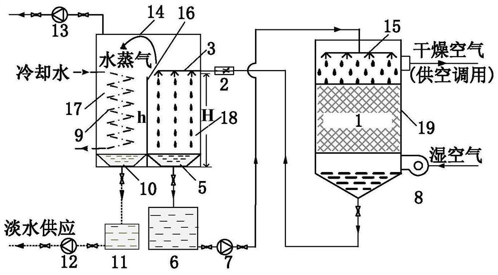
[0018] The technical solution of the present invention will be further described below in conjunction with the accompanying drawings and specific embodiments.

[0019] Such as Figure 1~2 As shown, the present invention is based on the flash regeneration solution dehumidification and fresh water production composite system, which can integrate the solution dehumidification and fresh water production into one system, and the solution regeneration and fresh water production are carried out in the low-pressure flash regenerator 14 at the same time The composite system of the present invention includes a solution dehumidification circulation loop composed of a dehumidifier 19 and a flash regenerator 14; a dehumidification filler 1 is provided in the dehumidifier 19, and a liquid distributor 15 is arranged on the top of the dehumidification filler 1, and the phase change dehumidification liquid passes through The liquid distributor 15 is sprayed on the dehumidification packing 1, a...


PUM


Abstract

The invention discloses a solution dehumidification and fresh water production combined system based on flash evaporation regeneration. The system comprises a solution dehumidification circulation loop consisting of a dehumidifier and a flash evaporation regenerator; dehumidification packing is arranged in the dehumidifier, a solution distributor is arranged at the upper part of the dehumidification packing, a phase change dehumidification solution is sprayed to the dehumidification packing through the solution distributor, and wet air enters the dehumidifier from the lower part of the dehumidifier through a fan; the flash evaporation regenerator comprises a condensation pipe and a spray pipe, and the condensation pipe forms a cooling water circulation loop with an external cooling water pool through a pipeline; the dehumidified dry air is discharged from an exhaust port formed in the upper part of the dehumidifier, the phase change dehumidification solution which is diluted and subjected to heat absorption enters the flash evaporation regenerator through a connecting pipeline and is sprayed out through the spray pipe in the flash evaporation regenerator, and steam which is formedby flash evaporation at the spray-out moment of the phase change dehumidification solution forms a liquid under the action of the condensation pipe and the liquid is collected by a water collecting tray; and the phase change dehumidification solution which is not subjected to flash evaporation enters a solution tank, is fed into the dehumidifier through a solution pump and is sprayed out through the solution distributor to be dehumidified again.

Description

technical field [0001] The invention relates to a composite system for solution dehumidification and fresh water production based on flash regeneration. Background technique [0002] In the field of refrigeration and air conditioning, the existing research has conducted a lot of positive and beneficial explorations on the performance improvement of the solution dehumidification and regeneration process. In the process of dehumidification / regeneration of the solution, the water in the air is absorbed and the water in the solution is vaporized, respectively, accompanied by the mass migration of water entering / leaving the solution, and the latent heat transfer of the phase change of water also occurs, resulting in an increase or decrease in the temperature of the solution. This change in the thermodynamic state of the solution will further restrict the heat and mass exchange efficiency of the dehumidification / regeneration process. In theory, the greater the mass migration of wa...

Claims


Application Information

Patent Timeline
IPC IPC(8): F24F3/14E03B3/28H02S40/32
CPCF24F3/1411E03B3/28H02S40/32F24F2003/1458Y02E10/50
Inventor 牛晓峰董红林夏芮峰王丹丹高鹏段地长何旭
Owner NANJING UNIV OF TECH
Why Eureka
Try Eureka