
Axial force balance structure of boost air flotation turbine cooler

A technology of turbine cooler and balanced structure, which is applied in the cooling of turbine/propulsion device, engine cooling, non-variable pump, etc. It can solve problems such as unfavorable rotor starting, accelerated bearing wear, and shortened bearing service life. Achieve the effect of solving the floating problem of the booster air bearing turbine

Active Publication Date: 2020-10-13
XINXIANG AVIATION IND GROUP +1
View PDF13 Cites 2 Cited by
  • Summary
  • Abstract
  • Description
  • Claims
  • Application Information

AI Technical Summary

Problems solved by technology

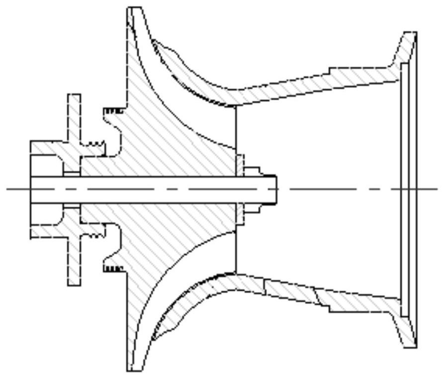
When the rotor is stationary, the air-bearing rotor is tightly wrapped by the elastic foil of the bearing, which generates additional friction for the rotor to start. In addition, because the air flow from the compressor inlet to the turbine outlet is a throttling process, the pressure gradually decreases to atmospheric pressure. This results in a pressure differential between the compressor inlet and the turbine outlet ( figure 2 ), the pressure difference produces an axial force P1 directed from the compressor to the turbine (see figure 1 ), which is not conducive to the starting of the rotor. At the same time, it also accelerates the wear of the bearing and shortens the service life of the bearing

Method used


Image

  • Axial force balance structure of boost air flotation turbine cooler
  • Axial force balance structure of boost air flotation turbine cooler
  • Axial force balance structure of boost air flotation turbine cooler

Examples


Embodiment Construction

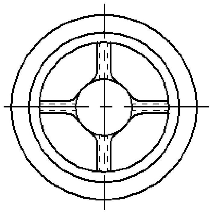
[0017] The present invention will be described in further detail below. see image 3 , the structure of the axial force balance of the aviation booster air flotation turbine cooler is shown in image 3 , which consists of compressor volute 1, compressor impeller 2, shaft 3, dynamic sealing ring 4, self-locking nut 5 and tie rod 6. The compressor impeller 2 is pressed into the shaft 3 hole, the tie rod 6 passes through the shaft 3 and the compressor impeller 2, the self-locking nut 5 is installed on the tie rod 6, and compresses the dynamic sealing ring 4; the compressor volute 1 is fixed by screws in the shell;

[0018] A dynamic sealing ring 4 is added to the shaft head of the compressor impeller 2, and a guide device is arranged at the inlet of the compressor volute 1, and a hole is opened in the middle of the device to form a seal with the dynamic sealing ring 4. The ribs of the flow guiding device are provided with pressure relief holes communicating with the outside in...


PUM


Abstract

The invention belongs to the technical field of aviation turbine coolers, and relates to axial force balance of a pod environmentally controlled turbine cooler, in particular to an axial force balancestructure of a pod environmentally controlled boost air flotation turbine cooler. The structure is composed of a compressor volute, a compressor impeller, a shaft, a dynamic sealing ring, a self-locking nut and a pull rod. The compressor impeller is pressed into a hole of the shaft, the pull rod penetrates through the shaft and the compressor impeller, the dynamic sealing ring is arranged on a shaft head of the compressor impeller, and the self-locking nut is installed on the pull rod and compresses the dynamic sealing ring; the compressor volute is fixed to a housing through screws; a diversion device is arranged at an inlet of the compressor volute, a hole is formed in the middle of the diversion device to form a seal with the dynamic sealing ring, and the compressor volute and the dynamic sealing ring form a cavity A. A novel structure floating device greatly reduces or even eliminates the axial force and additional friction torque during the rotor starting process, the floating problem of a boost air flotation turbine is fundamentally solved, and compared with a general structure, the novel structure has great advantages.

Description

technical field [0001] The invention belongs to the technical field of aviation turbine coolers, and relates to axial force balance of a turbine cooler, in particular to an axial force balance structure of a pressurized air flotation turbine cooler. Background technique [0002] The air bearings of aviation turbine coolers use air as the lubricating medium, do not require external bleed air, have no oil pollution, no contact friction, high speed, long life, and high reliability, and are widely used to replace ball bearings. The structure of the current boosted air-floating turbo-compressor can be found in figure 1 , which consists of compressor volute, compressor impeller, shaft, washer, self-locking nut and tie rod. The compressor impeller is pressed into the shaft hole, the pull rod passes through the shaft and the compressor impeller, the self-locking nut is installed on the pull rod, and the washer is pressed; the compressor volute is fixed on the casing by screws. Whe...

Claims


Application Information

Patent Timeline
Patent Type & Authority Applications(China)
IPC IPC(8): F04D29/051F04D29/12F04D29/42F04D29/44F04D29/02F04D29/32F02C7/12
CPCF02C7/12F04D29/023F04D29/051F04D29/122F04D29/321F04D29/4206F04D29/441
Inventor 张永革王超吴会军包胜赵磊高鹏飞邓波
Owner XINXIANG AVIATION IND GROUP
Learn More