
High-efficiency hydraulic twisting machine capable of staggering orifice

A pipe twisting machine, high-efficiency technology, applied in the direction of drill pipe, casing, drilling equipment, etc., can solve the problem of unscrewing and unloading the axial floating of the drill pipe, the pipe twisting machine has no automatic centering function, and the drill pipe and the impact of equipment life, etc., to achieve the effect of large torque, prolong life, and reduce labor intensity

Inactive Publication Date: 2012-11-14
CHINA UNIV OF GEOSCIENCES (WUHAN)
View PDF0 Cites 0 Cited by
  • Summary
  • Abstract
  • Description
  • Claims
  • Application Information

AI Technical Summary

Problems solved by technology

[0004] 1. Most of the existing pipe twisters are suitable for unscrewing and unloading drill pipes with cuts. The cuts will greatly reduce the strength of the drill pipes, thereby affecting the drilling construction process. However, the pipe twisters suitable for unscrewing outer flat drill pipes are still unavailable. No
[0005] 2. Most of the existing pipe twisting machines are suitable for unscrewing drill pipes in the case of medium and shallow holes or small torque. Equipment life has a big impact
[0006] 3. The existing pipe twisting machine does not solve the axial floating problem in the process of unscrewing and unloading the drill pipe well, which results in aggravated wear of the drill pipe thread
[0007] 4. The existing pipe twisting machine has no automatic centering function
When the upper and lower drill pipes are docked, if the centers of the two drill pipes are not in a straight line, it is easy to screw up and damage the threads during the docking, thus shortening the service life of the drill pipes

Method used


Image

  • High-efficiency hydraulic twisting machine capable of staggering orifice
  • High-efficiency hydraulic twisting machine capable of staggering orifice
  • High-efficiency hydraulic twisting machine capable of staggering orifice

Examples


Embodiment Construction

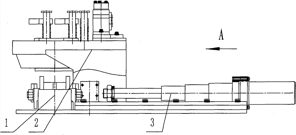
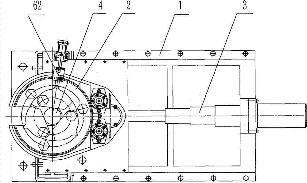
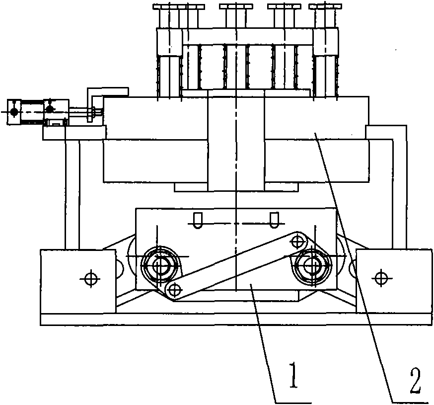
[0038] A high-efficiency hydraulic pipe wringer that can open the orifice of the present invention is mainly composed of the following parts:

[0039] (1) Lower clamp: The lower clamp clamps the drill pipe at the lower section of the hole, supports the self-weight of the drill pipe in the drill pipe hole, overcomes the pre-tightening or punching torque, and prevents the upper drill pipe from rotating or slipping in the hole when it is unscrewed. .

[0040] (2) Upper tong: The upper tong mainly completes the axial telescopic compensation in the process of clamping, screwing / unloading and unscrewing of the upper drill pipe.

[0041] (3) Horizontally move hydraulic cylinder 3 (get out of the orifice): due to the limited space in the orifice, horizontally move the hydraulic cylinder to retreat to the edge of the hole when the pipe twister does not need to be used, so as to facilitate the operation of the orifice.

[0042] (4) Hydraulic system part: The pipe twisting machine adopt...


PUM


Abstract

The invention relates to high-torque hydraulic twisting equipment applied to an external flush drill stem and belongs to the field of drilling and exploring machinery. A high-efficiency hydraulic twisting machine capable of staggering an orifice is characterized by comprising a lower tong, an upper tong, and a horizontally moving hydraulic cylinder. A lower end slider of a frame of the upper tongis positioned in an upper tong sliding guide slot on a lower tong frame of the lower tong; a cylinder body of the horizontally moving hydraulic cylinder is fixed on a horizontally moving hydraulic cylinder fixing plate on the lower tong frame of the lower tong; and a piston rod of the horizontally moving hydraulic cylinder is hinged with the lower part of the frame of the upper tong. The twistingmachine is applied to mechanical twisting for the external flush drill stem, can realize all technical actions of centering, screwing, floating, punching / pre-tightening, and has the advantages of high torque, small volume, reliable and safe work, and simple operation.

Description

technical field [0001] The invention relates to a high-torque hydraulic unscrewing device suitable for an outer flat drill pipe, which belongs to the field of drilling machinery. Background technique [0002] Most of the pipe twisters in drilling engineering are only suitable for drill pipes with cuts. The clamping part usually uses pad forks, and the unscrewing part uses free pliers. Rotation, so as to realize the unscrewing and unloading of the drill pipe, the control part generally adopts mechanical operation and hydraulic operation. [0003] The deficiencies of the existing pipe wringer: [0004] 1. Most of the existing pipe twisters are suitable for unscrewing and unloading drill pipes with cuts. The cuts will greatly reduce the strength of the drill pipes, thereby affecting the drilling construction process. However, the pipe twisters suitable for unscrewing outer flat drill pipes are still unavailable. No. [0005] 2. Most of the existing pipe twisting machines are...

Claims


Application Information

Patent Timeline
Patent Type & Authority Patents(China)
IPC IPC(8): E21B19/18
Inventor 李波朱文林张琦王院生张国栋曾志军高厚秀张萌王玉丹许华松周红心
Owner CHINA UNIV OF GEOSCIENCES (WUHAN)
Learn More