
Automatic wind turbine generator fixing device

A technology for wind turbines and fixtures, which is applied in the assembly of wind turbines, the configuration of installation/support of wind turbines, and wind power generation, etc., can solve the problem of increasing installation and operation costs of offshore wind turbines, increasing installation costs, and wasting installation time. problems, to achieve the effect of reducing installation and operation costs, facilitating adjustment, and reducing installation costs

Inactive Publication Date: 2020-10-13
张恒
View PDF0 Cites 0 Cited by
  • Summary
  • Abstract
  • Description
  • Claims
  • Application Information

AI Technical Summary

Problems solved by technology

[0003] In the process of installing the support cylinder, due to the height limitation, it is necessary to use a large hoisting machine to complete the hoisting operation, and after installing the support cylinder, it is necessary to use a large hoisting machine to hoist the machine head to the support cylinder, and then Then the blades are hoisted on the machine head separately, thereby completing the installation of the wind turbine, so the waste of installation time is caused, and the installation cost is increased through large-scale hoisting equipment, which further increases the offshore wind power generation. Machine installation and operating costs

Method used


Image

  • Automatic wind turbine generator fixing device
  • Automatic wind turbine generator fixing device
  • Automatic wind turbine generator fixing device

Examples


Embodiment Construction

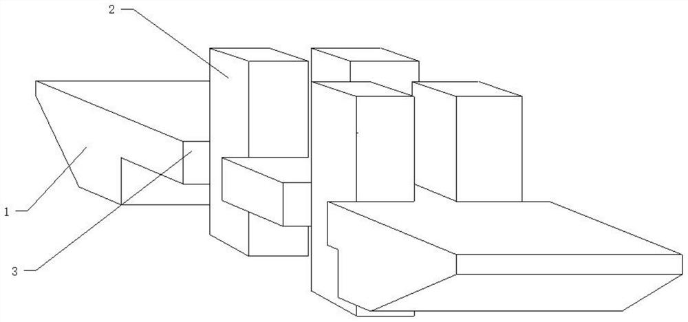
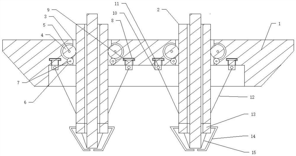
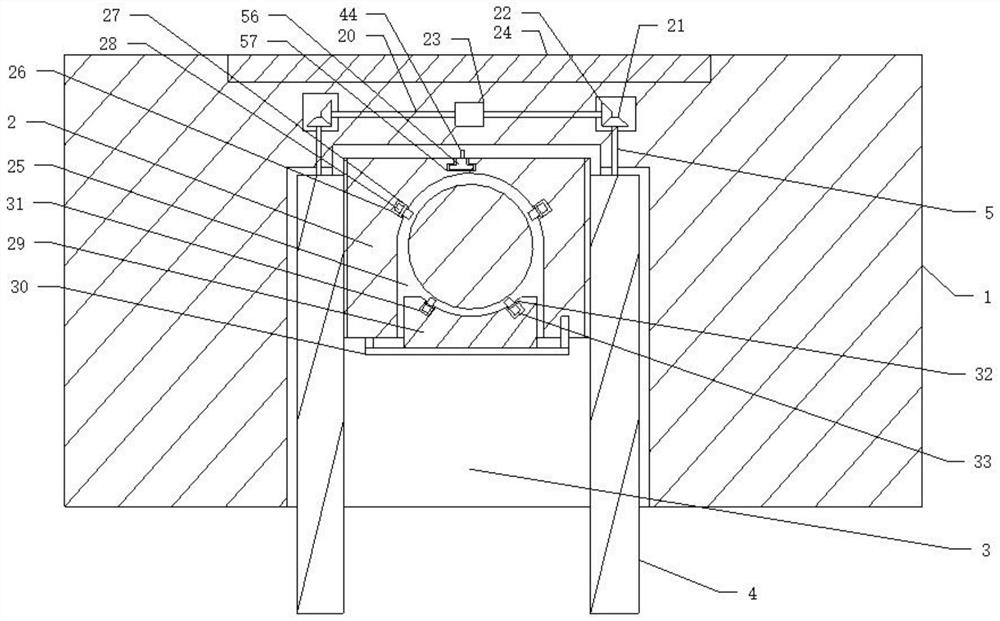
[0035] Such as Figure 1 to Figure 9 As shown, an automatic fixing device for a wind power generator includes a hull 1, with hull side grooves 3 provided on both sides of the hull 1, and a vertical support tube 2 that slides vertically in the hull side groove 3, A support base 13 is provided at the bottom of the vertical support cylinder 2, a support cylinder groove 25 is provided on the vertical support cylinder 2, and a wind support cylinder 19 is provided in the support cylinder groove 25. 2 is also provided with a swinging lock block 29, the lock block 29 restricts the swing of the wind support cylinder, the conveying support cylinder 2 is provided with a rotating control shaft 40, the control shaft 40 controls the The swing of the lock block 29 is described.

[0036] The hull 1 can float on the water. Hull side tanks 3 are provided on both sides of the hull 1. The number of hull side tanks 3 is set according to the needs of the design, and a vertical set is provided in the ...


PUM


Abstract

The invention discloses an automatic wind turbine generator fixing device. The device comprises a hull, wherein hull side grooves are formed in the two sides of the hull, and vertical supporting cylinders sliding vertically are arranged in the hull side grooves; one supporting base is arranged at the bottom of each vertical supporting cylinder, one supporting cylinder groove is formed in each vertical supporting cylinder, and wind power supporting cylinders are arranged in the supporting cylinder grooves; transverse gear shafts for supporting the vertical supporting cylinders to slide are arranged on the two sides of the hull side grooves correspondingly, and transverse sliding blocks sliding in the hull are further arranged on the two sides of the hull side grooves correspondingly; and one supporting module is arranged on each transverse sliding block correspondingly, one rotating first pull rope wheel is arranged in each supporting module correspondingly, and first pull ropes are connected to the vertical supporting cylinders correspondingly. Ascending and descending of the wind power supporting cylinders is controlled through the vertical supporting cylinders, so that the heightis adjusted, and the installation efficiency of the wind power supporting cylinders is greatly improved.

Description

Technical field [0001] The invention relates to an installation device for a wind power generator, in particular to an automatic fixing device for a wind power generator, in particular to an automatic fixing device for a wind power generator which can realize automatic lifting and convenient installation. Background technique [0002] With the promotion of wind power technology, the number of wind power installations has been continuously increased. Among the current support tubes, offshore wind power generation is increasing. Due to the advantages of offshore wind energy, offshore wind power generation has been vigorously promoted. In the process of installing the wind turbine, a fixed base needs to be installed in the sea, and then the support tube is fixedly installed on the fixed base, so that the wind generator can be supported and fixed. In the process of installing the support tube, a large hoisting installation is required. The equipment cooperates to complete the hoistin...

Claims


Application Information

Patent Timeline
IPC IPC(8): F03D13/25F03D13/10B63B35/44
CPCB63B35/44B63B2035/4466F03D13/10F03D13/25Y02E10/72Y02E10/727
Inventor 张恒
Owner 张恒
Learn More