Hydraulic vibration exciter

A technology of hydraulic exciter and shock wave, which is applied in the direction of vibrating fluid and fluid pressure actuating device, etc. It can solve the problems of large working resistance, difficult processing, unsuitable working environment with harsh conditions, etc., and achieves amplitude and The effect of stable vibration frequency, fast output response speed, smooth start and stop

Inactive Publication Date: 2003-08-13
许步勤
View PDF0 Cites 0 Cited by
  • Summary
  • Abstract
  • Description
  • Claims
  • Application Information

AI Technical Summary

Problems solved by technology

The exciter structure of this kind of vibrating seat is relatively complicated, and many holes and grooves are opened on the rotor, which brings great difficulties to the processing
In addition, this utility model can only generate a one-way exciting force in the direction vertical to the ground, so it can only be used in specific occasions such as vibrating seats, and cannot be used as a vibration source for vibrating machinery in industry
[0004] Since the above-mentioned hydraulic exciter can only be used for a specific working machine according to specific working conditions, it cannot meet the various needs of various working conditions. Moreover, the anti-pollution ability of the exciter is poor, and the working resistance is large, so it is not suitable For harsh working environments

Method used


Image

  • Hydraulic vibration exciter
  • Hydraulic vibration exciter
  • Hydraulic vibration exciter

Examples


Embodiment Construction

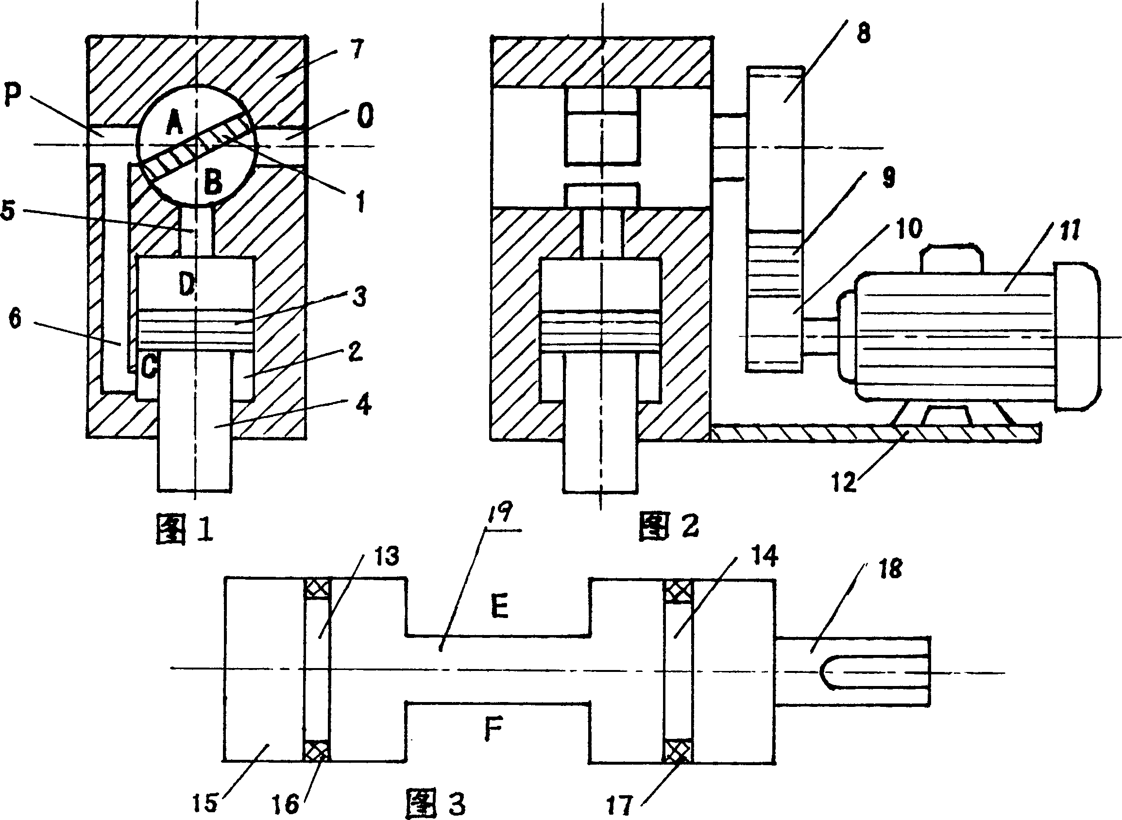
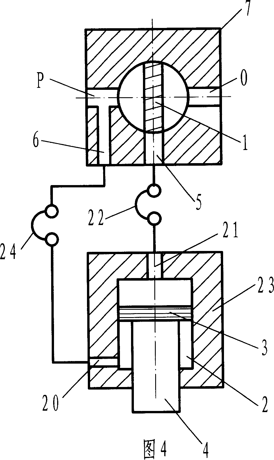
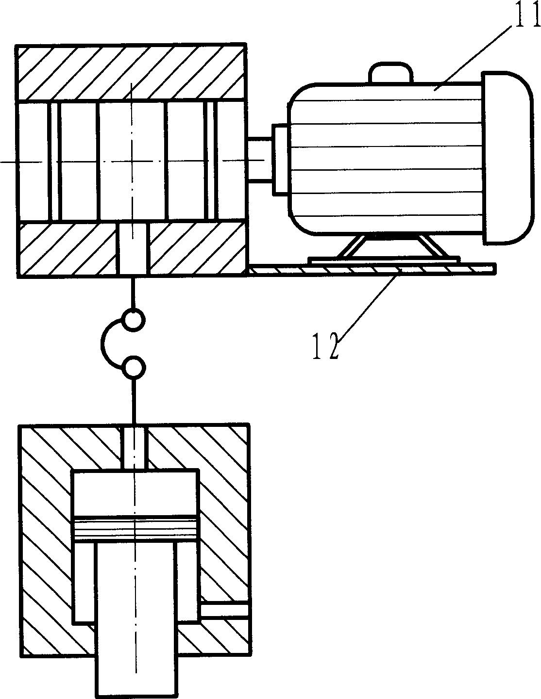
[0023] The hydraulic exciter shown in Fig. 1 and Fig. 2 is composed of a shock wave device 1, a hydraulic cylinder 2, a housing 7 and a drag element 11 of a drag device, a large pulley 8, a small pulley 10, a transmission belt 9, and a base 12 and so on. The shock wave device 1 is installed in the casing 7 and is located at the upper part of the piston cavity D of the hydraulic cylinder 2 . The casing 7 is provided with liquid holes 5 and 6 , and the shock wave 1 and the hydraulic cylinder 2 are communicated through the liquid holes 5 . The liquid hole 6 communicates with the high-pressure liquid inlet P and the piston rod cavity C of the hydraulic cylinder 2 . The high-pressure liquid inlet P, the liquid return port O and the liquid passage hole 5 are designed in the housing 7 on the same cross section, and the diameters of the three holes are equal. The high-pressure liquid inlet P and the liquid return port O are designed on the same center line, 180 degrees to each other...


PUM


Abstract

The hydraulic vibration exciter for vibration machinery comprises shock wave device, hydraulic cylinder and drive device, in which the shock wave is positioned at side of piston cavity of hydraulic cylinder, and is directly connected with drive device. Said hydraulic vibration exciter adopts single-stroke hydraulic cylinder, and the shock wave device and the hydraulic cylinder can be made into one body, also can be separated. When they are separated, it can use a vibration exciter to simultaneously control several hydraulic cylinders to output synchronous vibration. It uses high water base medium, and possesses stronger contamination-resisting property, and its structure is simple and work is reliable, and it is easy to implement automatic control.

Description

technical field [0001] The invention relates to a hydraulic vibration exciter with simple structure, which is suitable for vibrating machines that need to be excited. Background technique [0002] At present, the hydraulic exciter used in industrial production is generally composed of a vibration cylinder, a hydraulic control valve, an elastic element and a hydraulic system. The vibrating oil cylinder is a double-out rod differential oil cylinder, one end of which is used as a vibrating element, and the other end is connected with an elastic element. This exciter uses a hydraulic system to keep the vibration frequency stable and make it easy to adjust. Refer to the magazine "Heavy Machinery" No. 1, 1994, page 51 and the magazine "China Mechanical Engineering", No. 8, 1999, page 866. [0003] In addition, the utility model patent with application number 90211581 discloses a "hydraulic vibration seat". The hydraulic system of the "hydraulic vibration seat" includes a hydrau...

Claims


Application Information

Patent Timeline
Patent Type & Authority Patents(China)
IPC IPC(8): B06B1/18F15B15/14
Inventor 许步勤
Owner 许步勤
Why Eureka
Try Eureka