Bicycle parallel transmission connecting rod mechanism

A technology for transmission connecting rods and bicycles, which is applied to wheel transmissions, vehicle components, vehicle gearboxes, etc., can solve problems such as low transmission efficiency, and achieve the effects of small power loss, high transmission efficiency and smooth rotation.

Pending Publication Date: 2020-10-13
徐宇
View PDF0 Cites 0 Cited by
  • Summary
  • Abstract
  • Description
  • Claims
  • Application Information

AI Technical Summary

Problems solved by technology

[0003] In order to overcome the shortcomings of low transmission efficiency of the existing roller chain transmission mechanism, this technical solution proposes a four-link parallel transmission linkage mechanism with a new structure

Method used


Image

  • Bicycle parallel transmission connecting rod mechanism
  • Bicycle parallel transmission connecting rod mechanism
  • Bicycle parallel transmission connecting rod mechanism

Examples


Embodiment Construction

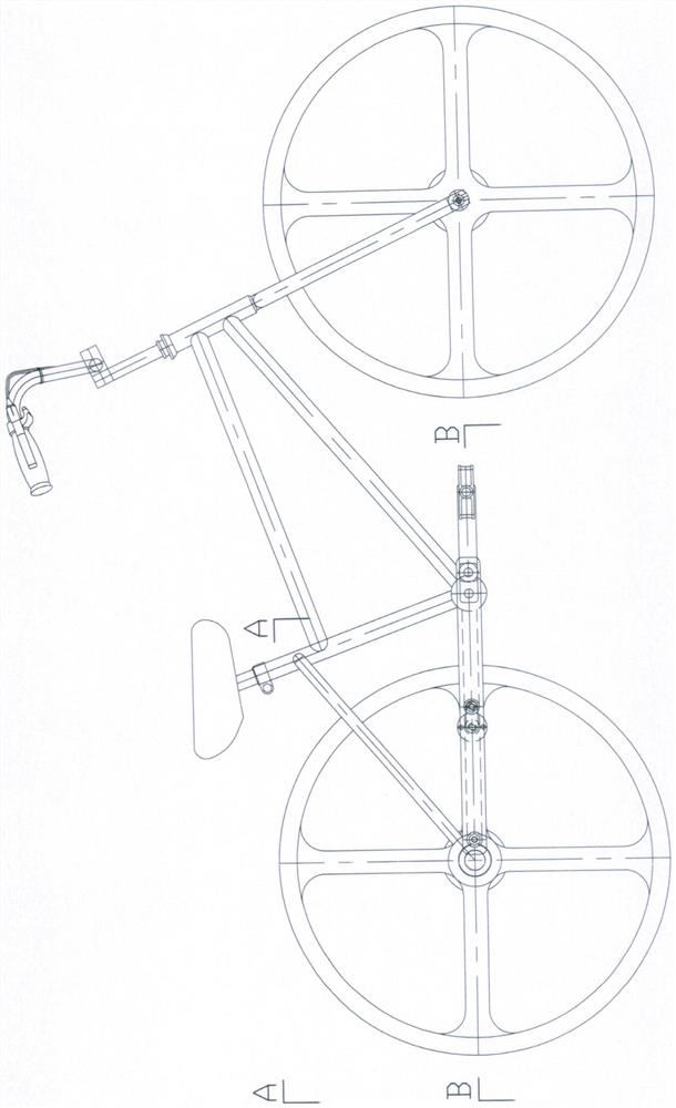
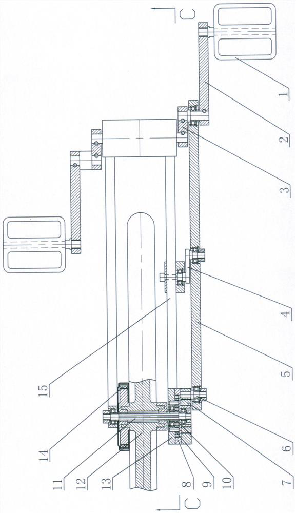
[0016] 1. The power transmission process of the parallel transmission linkage mechanism in sequence:

[0017] exist image 3 Middle: Pedal (1) → Pedal lever (2) → Pedal rotating short connecting rod (3) → Parallel transmission long connecting rod (5) → Flywheel rotating pin (6) → One-way live flywheel (7) → Increase High-speed planetary gear set ring gear (8) → speed-up planetary gear set planetary gear (9) → speed-up planetary gear set sun gear (10) → splined rear axle (11) → rear hub (12)

[0018] In the process of power transmission, the power drives the pedal rod (2) to rotate through the pedal (1), and the pedal rod (2) is tightly connected with the pedal rotating short connecting rod (3), thus driving the pedal to rotate the short connecting rod (3) Rotate so that the parallel drive long connecting rod (5) rotates in parallel along the rotation center of the pedal rotating short connecting rod (3), thereby driving the flywheel to rotate the pin (6) to rotate along the r...


PUM


Abstract

The invention discloses a bicycle parallel transmission connecting rod mechanism. According to the Figure 3 in the specification, the parallel transmission connecting rod mechanism is a whole set of low-cost transmission mechanism composed of a parallelogram four-connecting-rod transmission mechanism and a simple speed-increasing planetary gear set; power is sequentially transmitted to a set of parallel transmission connecting rod mechanism composed of a pedal rotating short connecting rod, a parallel transmission long connecting rod and a one-way movable flywheel through pedals and generatesrotation; the designed rotating radius of the pedal rotating short connecting rod is the same as the rotating radius of the one-way movable flywheel pin; then the power is transmitted to the speed-increasing planetary gear set through the one-way movable flywheel to rotate; and finally, the power is transmitted to a spline rear axle matched with the speed-increasing planetary gear set to drive a rear hub connected with the spline rear axle to rotate, so that the purpose of power transmission is achieved. Meanwhile, in order to prevent the parallel transmission long connecting rod from being dislocated and rotating reversely in the parallel rotating process of the parallelogram four-connecting-rod transmission mechanism, a short connecting rod for preventing reverse rotation caused by dislocation is arranged between the middle size position of the parallel transmission long connecting rod and the frame, and the rotating radius is the same as that of the pedal rotating short connecting rod, so that the parallel transmission long connecting rod is prevented from misplacing and reversing in the rotating process, and the pedal rotating short connecting rod and the one-way movable flywheel pin are forced to achieve the purpose of synchronously rotating in the same direction to output power.

Description

technical field [0001] The technical proposal relates to the transmission device in the power transmission process of bicycles, tricycles, electric bicycles and motorcycles, and is especially suitable for the transmission part between the bicycle pedal lever and the transmission part between the output power of the motorcycle engine and the driving wheel. Background technique [0002] At present, the transmission between the bicycle pedal lever and the rear wheel, and the transmission mechanism between the motorcycle engine assembly and the driving wheel are basically roller chain transmission, the transmission efficiency is about 0.9, and the energy consumption utilization rate is not high when riding. If the assembly accuracy between the one-way flywheel and the transmission chain is not adjusted properly, the phenomenon of jamming or chain falling will occur during riding. Moreover, most of the roller chain links are exposed to the air. In rainy and snowy weather for a lo...

Claims


Application Information

Patent Timeline
Patent Type & Authority Applications(China)
IPC IPC(8): B62M1/36B62M11/16B62M23/00
CPCB62M1/36B62M11/16B62M23/00
Inventor 徐宇
Owner 徐宇
Why Eureka
Try Eureka