Profile perforating device used in building field

A punching device, technology in the field, applied in positioning devices, boring/drilling, large fixed members, etc., can solve problems such as inability to place, achieve better use effect, easy to use, convenient and quick confirmation of punching positions Effect

Inactive Publication Date: 2020-10-13
许光福
View PDF0 Cites 1 Cited by
  • Summary
  • Abstract
  • Description
  • Claims
  • Application Information

AI Technical Summary

Problems solved by technology

[0003] At present, during the processing of building profiles, it is usually necessary to punch holes on the surface of the profiles. However, the existing punching devices still have certain deficiencies. During use, only fixed profiles can be punched. When other accessories are installed on the profile, it cannot be placed on the device for fixing. Therefore, it is urgent to design a profile punching device for the construction field to solve the above problems

Method used


Image

  • Profile perforating device used in building field
  • Profile perforating device used in building field
  • Profile perforating device used in building field

Examples


Embodiment 1

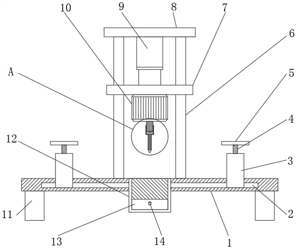
[0029] refer to Figure 1-5 , a profile punching device for the construction field, comprising a workbench 1 and support legs 11, the support legs 11 are arranged at four corners outside the bottom of the workbench 1, the top outer wall of the workbench 1 is fixedly connected with a column 6, and the column The top outer wall of the top plate 6 is fixedly connected with a top plate 8, and the bottom outer wall of the top plate 8 is fixedly connected with a hydraulic cylinder 9, and one end of the piston of the hydraulic cylinder 9 is fixedly provided with a lifting plate 7, and four corners of the bottom outer wall of the lifting plate 7 are provided with slides. hole, and the inner wall of the slide hole is slidably connected with the outer wall of the column 6, the bottom outer wall of the lifting plate 7 is provided with a punching mechanism, the both sides outer walls of the workbench 1 are provided with chute, and the inwall of the chute is provided with a limit mechanism....

Embodiment 2

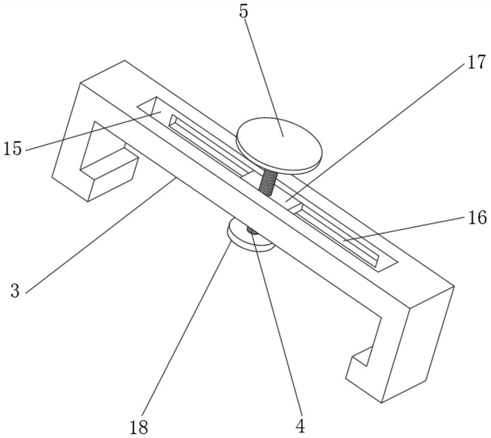
[0037] refer to Figure 6 , a profile punching device for the construction field. Compared with Embodiment 1, this embodiment also includes that the outer walls around the workbench 1 are fixedly connected with side plates 25, and the top outer walls of the side plates 25 are provided with limited holes. The inner wall of the bit hole is threadedly connected with a stud 26 , the top outer wall of the stud 26 is fixedly connected with a turntable 27 , and the bottom outer wall of the stud 26 is fixedly connected with a support plate 28 .

[0038] Working principle: when in use, turn the turntable 27 to drive the stud 26 on the side plate 25 to rotate, so that the support plate 28 at the bottom of the stud 26 moves down to cooperate with the support leg 11, and together play a supporting role for the device, so that when the device is working Not easy to shake, more stable.


PUM


Abstract

The invention discloses a profile perforating device used in the building field. The profile perforating device comprises a workbench and support legs. The support legs are arranged at four corners outside the bottom of the workbench. Stand columns are fixedly connected to the outer wall of the top of the workbench. A top plate is fixedly connected to the outer walls of the tops of the stand columns. A hydraulic cylinder is fixedly connected to the outer wall of the bottom of the top plate. An ascending-and-descending plate is fixedly arranged at one end of a piston of the hydraulic cylinder.Sliding holes are formed in four corners of the outer wall of the bottom of the ascending-and-descending plate. The inner wall of each sliding hole is connected with the outer wall of the corresponding stand column in a sliding manner. A perforating mechanism is arranged on the outer wall of the bottom of the ascending-and-descending plate. Sliding grooves are formed in the outer walls of the twosides of the workbench. A limiting mechanism is arranged on the inner wall of each sliding groove. By means of the profile perforating device, different types of profiles can be fixed and perforated;higher flexibility is achieved in the using process of the device; the device can play a role in fast fixing a drill bit; when the size of a drilled hole needs to be changed and the drill bit needs tobe replaced, a user only needs to rotate backwards a sleeve, and the drill bit can be taken down for replacement; and the device is quite convenient to use.

Description

technical field [0001] The invention relates to the technical field of building profile processing, in particular to a profile punching device for the building field. Background technique [0002] Building profiles are objects with certain geometric shapes made of iron or steel and materials with certain strength and toughness through rolling, extrusion, casting and other processes. According to the different smelting quality of steel, profile steel is divided into ordinary profile steel and high-quality profile steel. Ordinary section steel is divided into large section steel, medium section steel, and small section steel according to the current metal product catalogue. Ordinary section steel can be divided into I-beam, channel steel, angle steel, round steel, etc. [0003] At present, during the processing of building profiles, it is usually necessary to punch holes on the surface of the profiles. However, the existing punching devices still have certain deficiencies. Dur...

Claims


Application Information

Patent Timeline
Patent Type & Authority Applications(China)
IPC IPC(8): B23B41/00B23B47/00B23B51/12B23Q1/25B23Q3/18
CPCB23B41/00B23B47/00B23B51/12B23Q1/25B23Q3/18
Inventor 许光福
Owner 许光福
Why Eureka
Try Eureka