
3D printing system and method suitable for micro-gravity space environment

A 3D printing and space environment technology, applied in the field of 3D printing systems, can solve the problems affecting the mechanical properties and reliability of formed parts, the high forming ability of amorphous alloy glass, and the rapid heat dissipation of amorphous alloys, and achieve the distribution of components in the system. Compact and efficient, resistant to the influence of hot and cold circulation, and the effect of high adaptability to the space environment

Inactive Publication Date: 2020-10-13
HUAZHONG UNIV OF SCI & TECH
View PDF6 Cites 4 Cited by
  • Summary
  • Abstract
  • Description
  • Claims
  • Application Information

AI Technical Summary

Problems solved by technology

However, this technology still has the following technical problems: (1) the glass-forming ability of amorphous alloys is extremely high; (2) in an open environment, the heat loss of supercooled liquid amorphous alloys is very fast, which seriously affects the performance of amorphous alloys. viscosity
High viscosity will inevitably affect the diffusion connection, resulting in weak welding between layers, or even detachment, seriously affecting the mechanical properties and reliability of formed parts

Method used


Image

  • 3D printing system and method suitable for micro-gravity space environment
  • 3D printing system and method suitable for micro-gravity space environment
  • 3D printing system and method suitable for micro-gravity space environment

Examples


Embodiment Construction

[0033] In order to make the object, technical solution and advantages of the present invention clearer, the present invention will be further described in detail below in conjunction with the accompanying drawings and embodiments. It should be understood that the specific embodiments described here are only used to explain the present invention, not to limit the present invention. In addition, the technical features involved in the various embodiments of the present invention described below can be combined with each other as long as they do not constitute a conflict with each other.

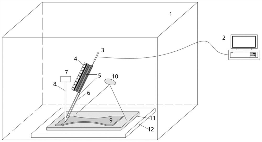
[0034] Aiming at the limitation of the payload launched by the rocket and the available space of the spacecraft, the present invention proposes a space 3D printing system suitable for the spacecraft. Such as figure 1 Shown is a schematic diagram of a 3D printing system suitable for a microgravity space environment according to an embodiment of the present invention. The 3D printing system inclu...


PUM

PropertyMeasurementUnit
glass transition temperatureaaaaaaaaaa
crystallization temperatureaaaaaaaaaa
diameteraaaaaaaaaa

Abstract

The invention discloses a 3D printing system suitable for a micro-gravity space environment. The 3D printing system comprises a housing (1) and a control unit (2) as well as a workbench (12) arrangedinside the housing (1), a base plate (11) arranged on the workbench (12), a feeding unit, and a processing head part, wherein the feeding unit comprises a storage device (4), a feeding mechanism (6) arranged at one end of the storage device (4) and an ejecting-out mechanism (3) arranged at the other end of the storage device (4); and the processing head part comprises a small laser unit (7). The invention further discloses a 3D printing method suitable for the micro-gravity space environment. The system avoids the crystallization risk that an amorphous alloy is connected and formed in a thermoplastic mode under a long-time high-temperature condition, can achieve coaxial feeding, is high in forming efficiency, guarantees uniform and continuous discharge, can form a part of any shape, can obtain a large-dimension amorphous alloy part with high forming quality, can keep good equipment work stability, and is especially suitable for on-track manufacturing in the space environment.

Description

technical field [0001] The invention belongs to the technical field of metal 3D printer manufacturing, and more specifically relates to a 3D printing system and method suitable for a microgravity space environment. Background technique [0002] With the rapid development of aerospace technology, research projects such as exploring deep space, building alien bases, and alien immigration will gradually be put on the agenda. However, to achieve long-term on-orbit material and life support, the construction of space application facilities, and the construction and operation of alien bases, it largely depends on how to achieve efficient, reliable, and low-cost "space manufacturing", so as to overcome the existing rocket launch. The method restricts space exploration activities in terms of load, volume, and cost. Space manufacturing can directly use space resources such as solar energy and raw materials to achieve self-sustainment. It is worth noting that the microgravity enviro...

Claims


Application Information

Patent Timeline
Patent Type & Authority Applications(China)
IPC IPC(8): B22F3/105B33Y10/00B33Y30/00
CPCB33Y10/00B33Y30/00
Inventor 李宁朱海红张宝鹏伍仕兴王怡龙廖海龙
Owner HUAZHONG UNIV OF SCI & TECH
Learn More