Power transformation cabinet dust-settling device

A technology of dust suppression device and substation cabinet, which is applied in the directions of substation/distribution device casing, substation/switchgear cooling/ventilation, substation/switch arrangement details, etc., can solve the problems of low efficiency and large dust in the substation cabinet, etc. Achieve the effect of ensuring safety, reducing failure rate and prolonging cleaning cycle

Active Publication Date: 2020-10-13
国网黑龙江省电力有限公司双鸭山供电公司 +1
View PDF13 Cites 0 Cited by
  • Summary
  • Abstract
  • Description
  • Claims
  • Application Information

AI Technical Summary

Problems solved by technology

[0004] The present invention is to solve the problem of large dust inside the outdoor substation cabinet and the low efficiency of existing dust removal methods, and now provides two types of dust suppression devices for substation cabinets

Method used


Image

  • Power transformation cabinet dust-settling device
  • Power transformation cabinet dust-settling device
  • Power transformation cabinet dust-settling device

Examples


specific Embodiment approach 1

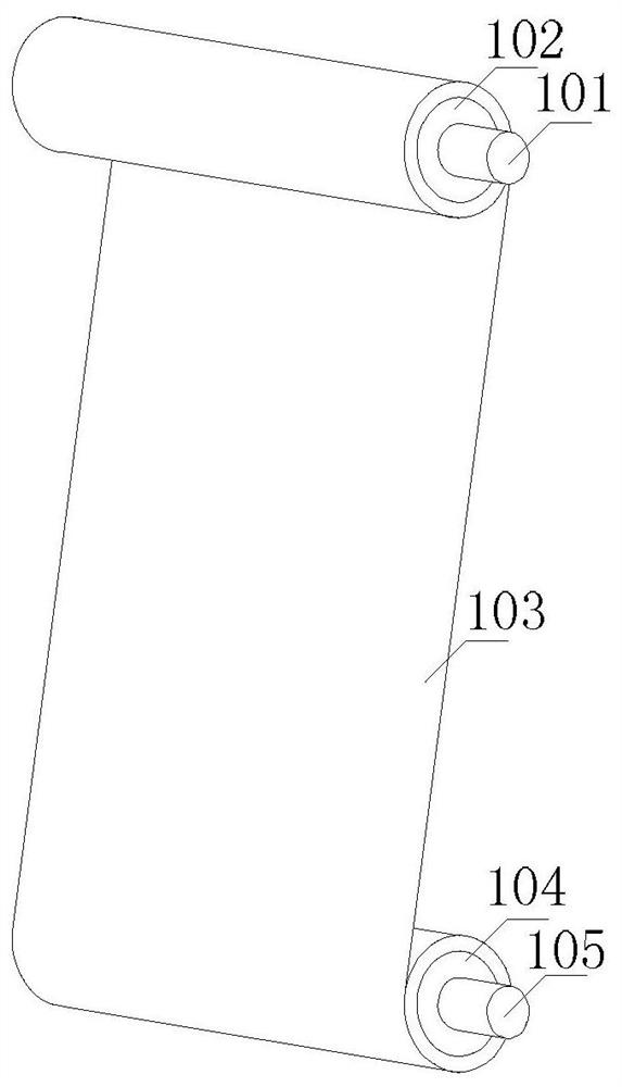
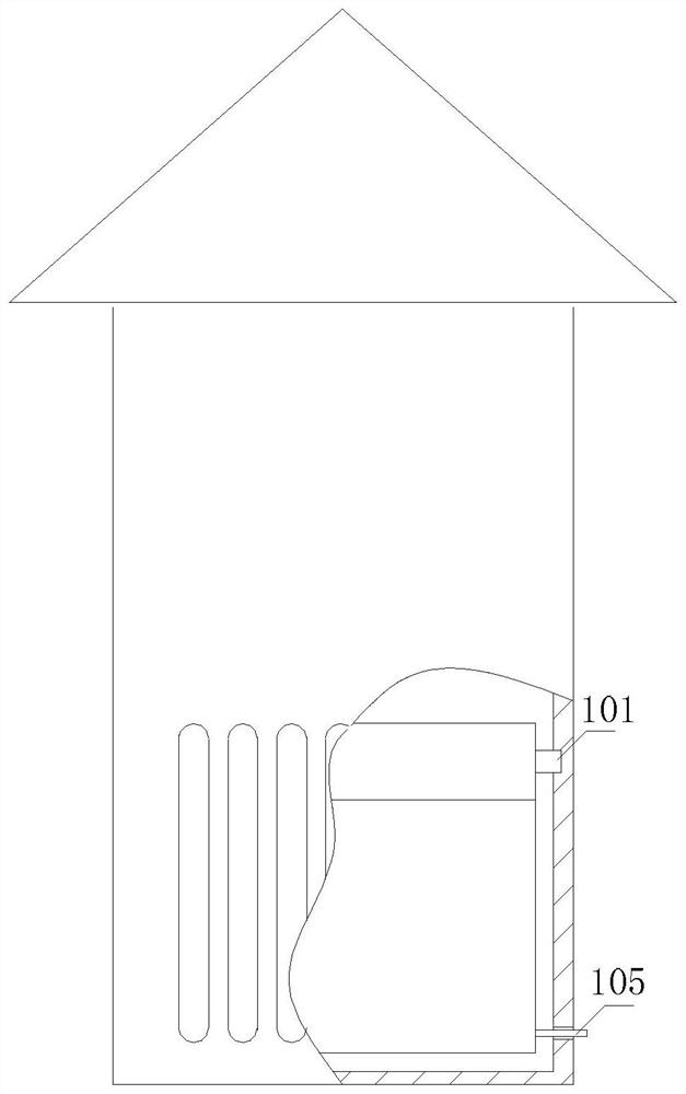
[0032] Specific implementation mode one: refer to figure 1 with figure 2 Describe this embodiment in detail. The dust suppression device for a transformer cabinet described in this embodiment includes: a support shaft 101 , a paper tube 102 , an electrostatic adsorption paper 103 , a driving roller 104 and a rotating handle 105 .

[0033] In practical application, the two ends of the support shaft 101 are respectively fixedly connected to the two opposite side walls of the transformer cabinet, so that the support shaft 101 is parallel to the side of the transformer cabinet with the ventilation opening. The paper tube 102 is sleeved on the support shaft 101 and can rotate. The electrostatic adsorption paper 103 is strip-shaped, and the head end of the electrostatic adsorption paper 103 is fixedly connected to the outer surface of the paper tube 102 , and is stacked and wound on the outer surface of the paper tube 102 to form a paper roll structure.

[0034] The driving rolle...

specific Embodiment approach 2

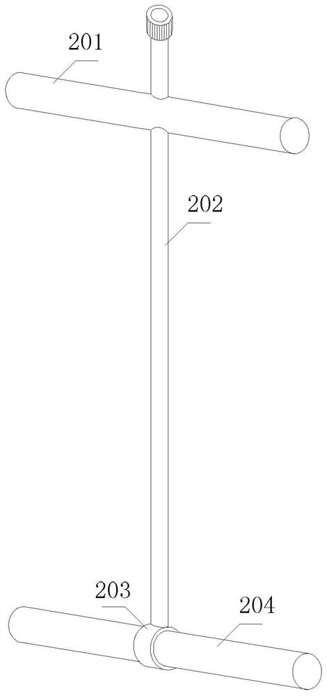
[0039] Specific implementation mode two: refer to Figure 3 to Figure 5 Describe this embodiment in detail. The dust suppression device for a transformer cabinet described in this embodiment includes: a bracket, two paper tubes 102, two sheets of electrostatic adsorption paper 103, a No. 1 motor 206, a No. 2 motor, a transmission belt 207, a controller, The motor driver, the dust sensor and the temperature sensor, and the support include: an upper cross bar 201 , a longitudinal bar 202 and a lower cross bar 204 .

[0040] The longitudinal bar 202 is perpendicular to the upper cross bar 201 and is fixedly connected with the midpoint of the upper cross bar 201. The upper cross bar 201 is close to the top of the longitudinal bar 202. The end of the longitudinal bar 202 is provided with a collar 203. The central axis of the longitudinal bar 202 The center axis of the collar 203 is perpendicular to each other. The collar 203 is sleeved on the outer surface of the lower cross bar 20...


PUM


Abstract

The invention provides a power transformation cabinet dust-settling device, and relates to the field of electrical equipment of an electric power system. The problems that dust in an outdoor power transformation cabinet is large, and an existing dust removal mode is low in efficiency are solved. A supporting shaft is used for being fixed in a power transformation cabinet. A paper tube is sleeved outside the supporting shaft and can rotate. The electrostatic adsorption paper is long-strip-shaped, the head end of the electrostatic adsorption paper is fixedly connected with the outer surface of the paper tube and wound on the outer surface of the paper tube in a stacked mode to form a paper roll structure, the driving roller is located under the paper tube, the tail end of the electrostatic adsorption paper is fixedly connected with the outer surface of the driving roller, and one end of the driving roller extends out of a rotating handle in the axial direction. The power transformation cabinet dust-settling device is suitable for an electric cabinet working in an outdoor area with large dust.

Description

technical field [0001] The invention belongs to the field of electrical equipment in a power system, and in particular relates to a dust reduction technology for a transformer cabinet. Background technique [0002] In power plants, variable voltage transmission is generally used to convert the generated electric energy into high voltage for transmission to reduce losses. Then the high voltage is converted into low voltage and delivered to the user. Therefore, it is necessary to use a transformer cabinet to centrally transform the voltage. Transformer cabinet is a factory prefabricated indoor and outdoor compact power distribution equipment arranged according to a certain wiring scheme, which organically combines functions such as transformer step-down and low-voltage power distribution. [0003] In urban areas, most transformer cabinets are located outdoors, and a large amount of dust often enters the cabinet. A large amount of dust accumulation will seriously affect the ...

Claims


Application Information

Patent Timeline
Patent Type & Authority Applications(China)
IPC IPC(8): B03C3/04B03C3/34B03C3/45B03C3/68H02B1/30H02B1/28H02B1/56
CPCB03C3/04B03C3/34B03C3/45B03C3/68H02B1/30H02B1/28H02B1/565
Inventor 吴宇高华为张晓海于晓刚赵忠颖
Owner 国网黑龙江省电力有限公司双鸭山供电公司
Why Eureka
Try Eureka