Impact test device and experimental method based on spatial motion sandwich plate structure

A technology of space motion and impact testing, applied in the testing of machine/structural components, impact testing, measuring devices, etc., can solve the problems of impact response behavior test simulation of composite sandwich panel structure, etc. Effect

Active Publication Date: 2020-10-09
HARBIN ENG UNIV
View PDF10 Cites 0 Cited by
  • Summary
  • Abstract
  • Description
  • Claims
  • Application Information

AI Technical Summary

Problems solved by technology

[0004] In order to solve the impact test of the existing fixing device, the present invention has the problem that it cannot be used for the test simulation of the impact response behavior of the composite sandwich plate structure in a moving state

Method used


Image

  • Impact test device and experimental method based on spatial motion sandwich plate structure
  • Impact test device and experimental method based on spatial motion sandwich plate structure
  • Impact test device and experimental method based on spatial motion sandwich plate structure

Examples


specific Embodiment approach 1

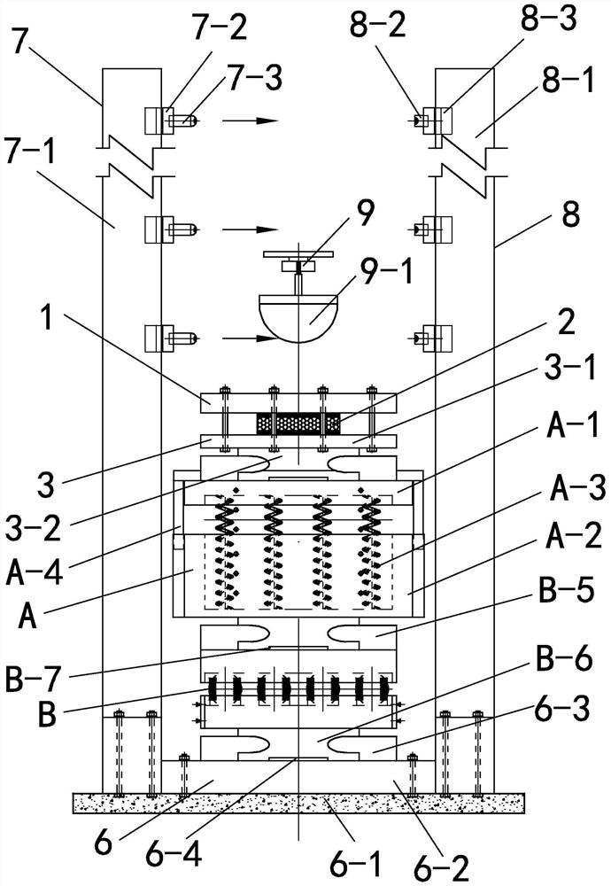
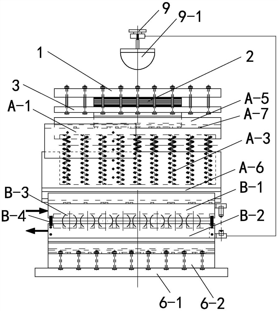
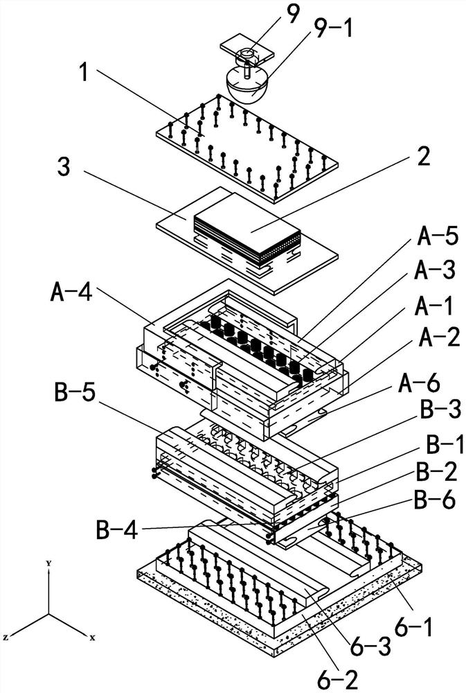
[0033] Specific implementation mode one: combine Figure 1 to Figure 7 Describe this embodiment, a kind of impact test device based on the space movement sandwich plate structure of this embodiment includes upper mounting splint 1, lower mounting splint 3, vertical plane vibration device A, horizontal plane motion device B, experimental base 6, signal The generating device 7 and the signal receiving device 8, the signal generating device 7 and the signal receiving device 8 are relatively arranged and installed on the experimental base 6, the horizontal plane moving device B is inserted on the experimental base 6, and the horizontal plane moving device B is located on the Between the signal generating device 7 and the signal receiving device 8, the vertical plane vibrating device A is plugged into the horizontal plane moving device B, the upper mounting splint 1 and the lower mounting splint 3 are buckled and the composite sandwich plate 2 is clamped, and the lower mounting spli...

specific Embodiment approach 2

[0041] Specific implementation mode two: combination Figure 1 to Figure 3 Describe this embodiment, the lower mounting splint 3 of this embodiment includes a lower splint 3-1 and a splint chute 3-2, and the splint chute 3-2 is fixedly installed on the lower end surface of the lower splint 3-1. Such setting facilitates cooperation and sliding insertion with the vertical plane vibration device A. Other compositions and connections are the same as in the first embodiment.

specific Embodiment approach 3

[0042] Specific implementation mode three: combination Figure 1 to Figure 3 Describe this embodiment, the vertical plane vibration device A of this embodiment includes an upper connection cover A-1, a lower connection cover A-2, a stopper A-4 and a plurality of vibration springs A-3, the lower connection cover A-2 A groove is opened in A-2, and multiple vibrating springs A-3 are installed in the lower connecting cover A-2, and the upper connecting cover A-1 is covered on multiple vibrating springs A-3, and the upper connecting cover A- 1 and the lower connection cover A-2 are connected by a stopper A-4, and the upper connection cover A-1 is located in the stopper A-4 and can float up and down under the action of the vibration spring A-3. Such arrangement facilitates vibration in the vertical direction. Other compositions and connections are the same as those in Embodiment 1 or Embodiment 2.

[0043] The setting of the limiter in this embodiment ensures that the test structu...


PUM


Abstract

The invention relates to an impact testing device and an experimental method, in particular to an impact testing device and an experimental method based on a spatial motion sandwich plate structure. The invention aims to overcome the problem that an impact test of an existing fixing device cannot be used for test simulation of impact response behaviors of a composite sandwich plate structure in amoving state. A horizontal plane motion device is inserted into an experiment base, a vertical plane vibration device is inserted into the horizontal plane motion device, and an upper mounting clamping plate and a lower mounting clamping plate are buckled and clamp to mount a composite sandwich plate on the vertical plane vibration device. According to the invention, an impact signal excitation device guides a hammer head to fall down; and height and falling speed information corresponding to different positions of the impact hammer head at falling moments is measured through a signal generating device and a signal receiving device. The impact testing device is used for testing mechanical properties.

Description

technical field [0001] The invention relates to an impact testing device and an experimental method, in particular to an impact testing device and an experimental method based on a space-moving sandwich plate structure. Background technique [0002] Composite sandwich panel, or sandwich sandwich panel, is a typical sandwich energy-absorbing structure, which has the key functions of reducing the damage of the protected object when it is subjected to collision and impact, and improving the protective performance of the structure. Composite sandwich panels are mainly composed of panels made of metal materials or non-metal materials, and energy-absorbing materials between the panels. Usually, the impact test for composite sandwich panels is completed on a fixed device, that is, the test structure is installed on a fixed experimental device, and then the corresponding impact test is completed through impact equipment. [0003] In many engineering application environments, compos...

Claims


Application Information

Patent Timeline
IPC IPC(8): G01N3/303G01N3/02G01N3/06G01M7/08
CPCG01M7/08G01N3/02G01N3/06G01N3/068G01N3/303G01N2203/001G01N2203/0039G01N2203/0635G01N2203/0641G01N2203/0676G01N2203/0682
Inventor 路胜卓吴限德马加路陈卫东马敬鑫高天森吴世博陈光
Owner HARBIN ENG UNIV
Why Eureka
Try Eureka