Injection mould with water blowing device

An injection mold and mold technology, applied in the field of injection molds with a water blowing device, can solve the problems that the water tank cannot be blown, the water in the water tank cannot be completely blown, and rust, etc., to achieve acceleration, reduce consumption, and avoid production. rust effect

Inactive Publication Date: 2020-10-09
YANCHENG INST OF TECH
View PDF4 Cites 0 Cited by
  • Summary
  • Abstract
  • Description
  • Claims
  • Application Information

AI Technical Summary

Problems solved by technology

[0003] When the current injection mold is in use, a water blowing device is usually added to the water cooling device of the injection mold, which can prevent the metal parts from rusting due to the moisture remaining in the mold after the water cooling is completed. However, most of the existing water blowing devices use Blowing water is realized by wind force. In this way of blowing water, some parts of the corners of the sink cannot be blown in actual use, so that the water in the sink cannot be blown completely, and the metal parts at the corners will still rust. Therefore, we need to design an injection mold with a water blowing device to improve such problems

Method used


Image

  • Injection mould with water blowing device
  • Injection mould with water blowing device
  • Injection mould with water blowing device

Examples


Embodiment 1

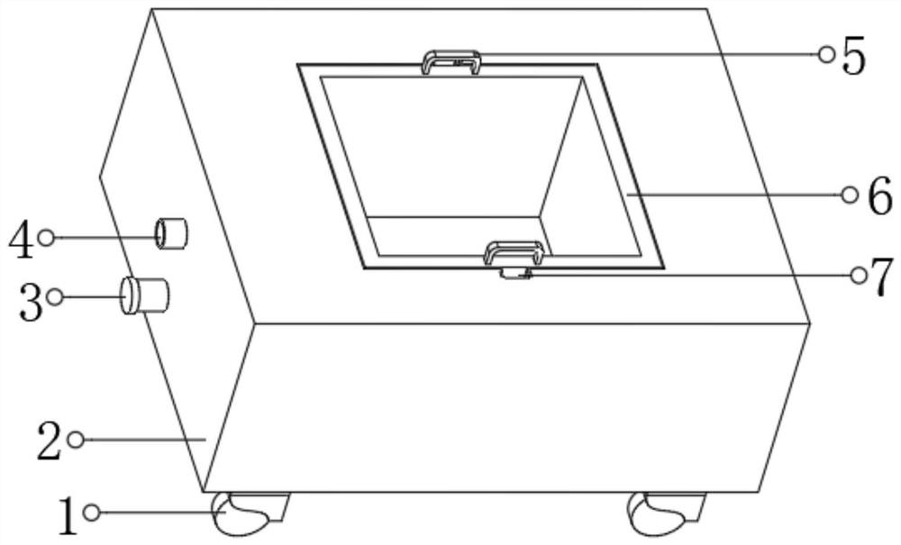
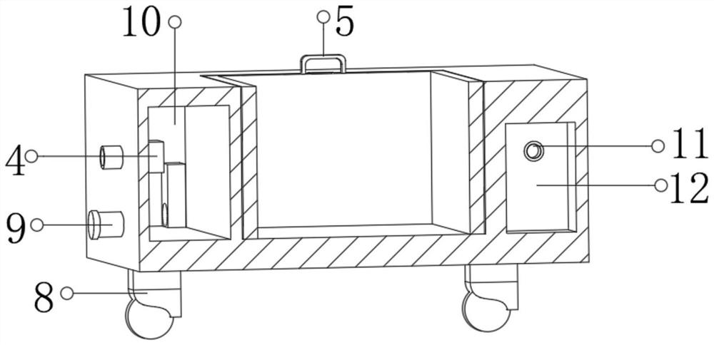
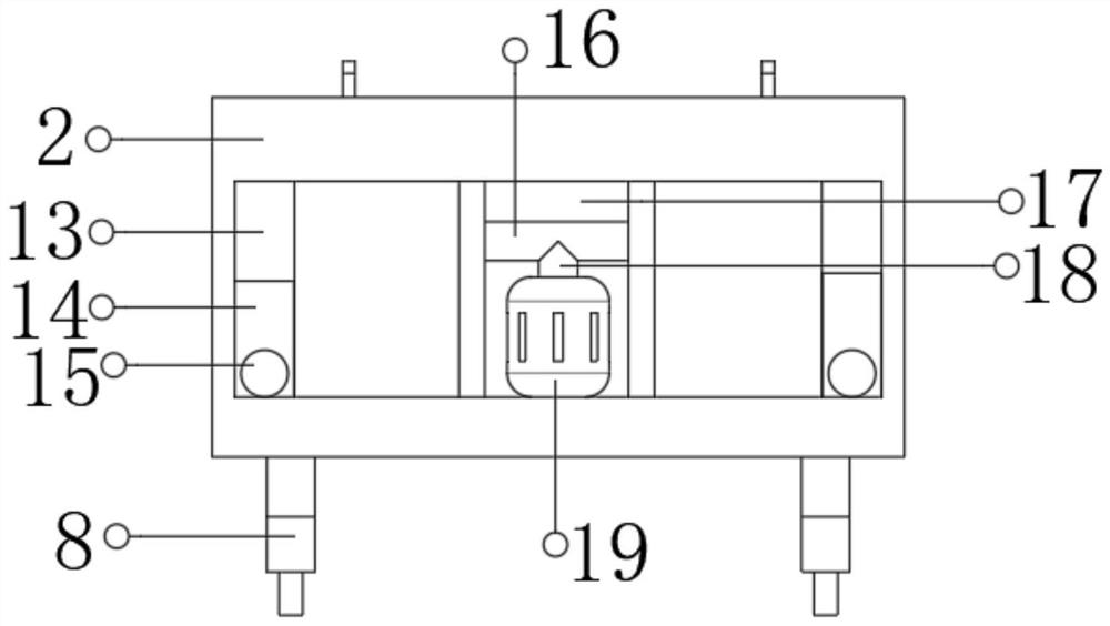
[0026] refer to Figure 1-3 , an injection mold with a water blowing device, including a mold body 2, a groove is opened on the outer wall of the top of the mold body 2, and chute 7 is opened on the inner wall at both ends of the groove, and the outer walls of the two chute 7 slide A mold cavity 6 is connected, a water storage tank 10 is arranged inside one end of the mold body 2, a water tank 13 is opened inside the two ends of the mold body 2, and a water retaining plate 14 is arranged between the water tank 13 and the water storage tank 10, two water retaining plates 14 The height is lower than the inner wall of the top of the water tank 13, and a round hole 15 is opened on the outer wall of the two water baffles 14 near the bottom, and the outer wall of one side of the two water tanks 13 is connected with a riser 12 by bolts, and the riser 12 There is an air inlet 11 on the surface, an air pressure box 17 is arranged between the two vertical plates 12, and the inner wall o...

Embodiment 2

[0030] refer to Figure 4 , an injection mold with a water blowing device. Compared with Embodiment 1, the two ends of the top outer wall of the mold body 2 are connected with pillars 23 by bolts, and the top outer walls of the pillars 23 are connected with a top plate 21 by bolts. The bottom outer wall of the top plate 21 is connected with an electric telescopic rod 22 by bolts, and the bottom outer wall of the electric telescopic rod 22 is connected with a limit rod 20 by bolts.

[0031] Working principle: When in use, when in use, first add an appropriate amount of water into the water storage tank 10 through the water inlet pipe 4, and the water in the water storage tank 10 flows into the two water tanks 13 through the round hole 15 on the water retaining plate 14, when injection molding When the volume of the model is relatively large, a large amount of water can be injected to make the water overflow directly from the upper part of the water baffle 14, so that the water ...


PUM


Abstract

The invention discloses an injection mould with a water blowing device. The injection mould comprises a mould body, and a groove is formed in the outer wall of the top of the mould body. Sliding chutes are formed in the inner walls of the two ends of the groove, and the outer wall of one side of each of the two sliding chutes is glidingly connected with a mould chamber. A water storage tank is arranged in one end of the mould body, and water channels are formed in the two ends of the mould body. Water baffles are arranged between the water channels and the water storage tank, and circular holes are formed in the positions, close to the bottoms, of the outer walls of one sides of the two water baffles. Vertical plates are fixedly arranged on the outer walls of one sides of the gathering ends of the two water channels, and air inlets are formed in the surfaces of the vertical plates. An air pressure box is arranged between the two vertical plates, and a pressure pump is fixedly arrangedon the inner wall of the bottom of the air pressure box. An air guide tube is fixedly arranged on the outer wall of the top of the pressure pump, and a horizontal tube is fixedly arranged on the outerwall of the top of the air guide tube. The injection mould can make use of air pressure to treat water attached to the surfaces of the water channels, so that the water can be treated completely to avoid rust inside the water channels, and meanwhile demoulding operation is conveniently carried out through a pull ring.

Description

technical field [0001] The invention relates to the technical field of injection molds, in particular to an injection mold with a water blowing device. Background technique [0002] Injection molding, also known as injection molding, is a molding method of injection and molding. The advantages of the injection molding method are fast production speed, high efficiency, automatic operation, various designs and colors, simple to complex shapes, large to small sizes, accurate product sizes, easy replacement of products, and complex shapes. Parts, injection molding is suitable for mass production and complex shape products and other molding processing fields. [0003] When the current injection mold is in use, a water blowing device is usually added to the water cooling device of the injection mold, which can prevent the metal parts from rusting due to the moisture remaining in the mold after the water cooling is completed. However, most of the existing water blowing devices use...

Claims


Application Information

Patent Timeline
IPC IPC(8): B29C45/73B29C45/17B29C45/26
CPCB29C45/1756B29C45/2602B29C45/73
Inventor 夏文胜皮立志
Owner YANCHENG INST OF TECH
Why Eureka
Try Eureka