
Injection mold device capable of discharging residual gas during injection molding

A technology of injection molding and injection mould, which is applied in the field of injection mould, can solve problems such as prone to printing, high air pressure, etc., and achieve the effect of tight film

Inactive Publication Date: 2020-10-09
周磊
View PDF0 Cites 3 Cited by
  • Summary
  • Abstract
  • Description
  • Claims
  • Application Information

AI Technical Summary

Problems solved by technology

[0006] Aiming at the deficiencies of the prior art, the present invention provides an injection mold device capable of discharging retained gas during injection molding, which has the advantages of convenient film opening, easy product fall-off, and the ability to discharge the retained gas in the casting cavity. In the technology, the injection molding solution entering the injection cavity can lead to excessive air pressure, resulting in the problem of easy printing

Method used


Image

  • Injection mold device capable of discharging residual gas during injection molding
  • Injection mold device capable of discharging residual gas during injection molding
  • Injection mold device capable of discharging residual gas during injection molding

Examples


Embodiment Construction

[0026] The following will clearly and completely describe the technical solutions in the embodiments of the present invention with reference to the accompanying drawings in the embodiments of the present invention. Obviously, the described embodiments are only some, not all, embodiments of the present invention. Based on the embodiments of the present invention, all other embodiments obtained by persons of ordinary skill in the art without making creative efforts belong to the protection scope of the present invention.

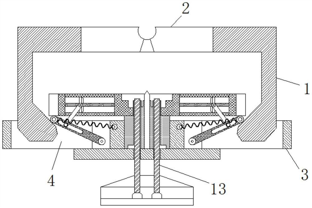
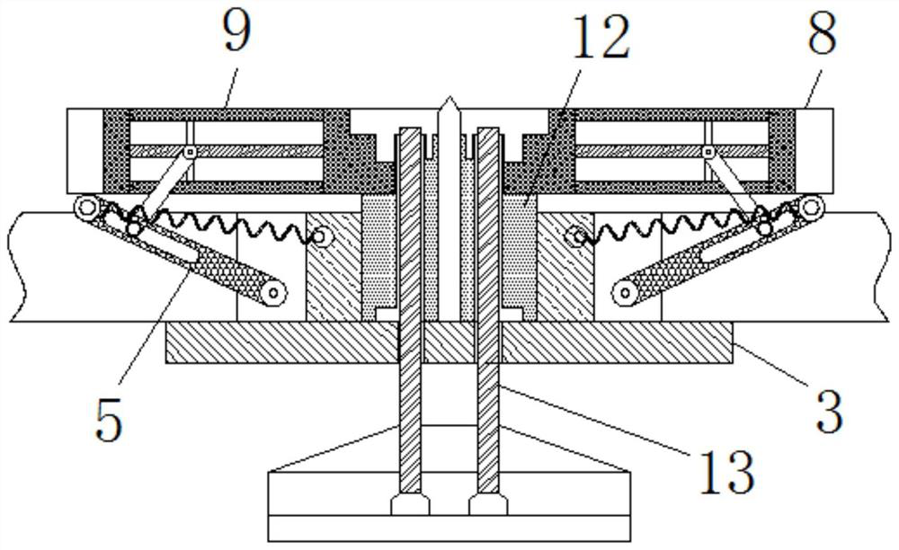
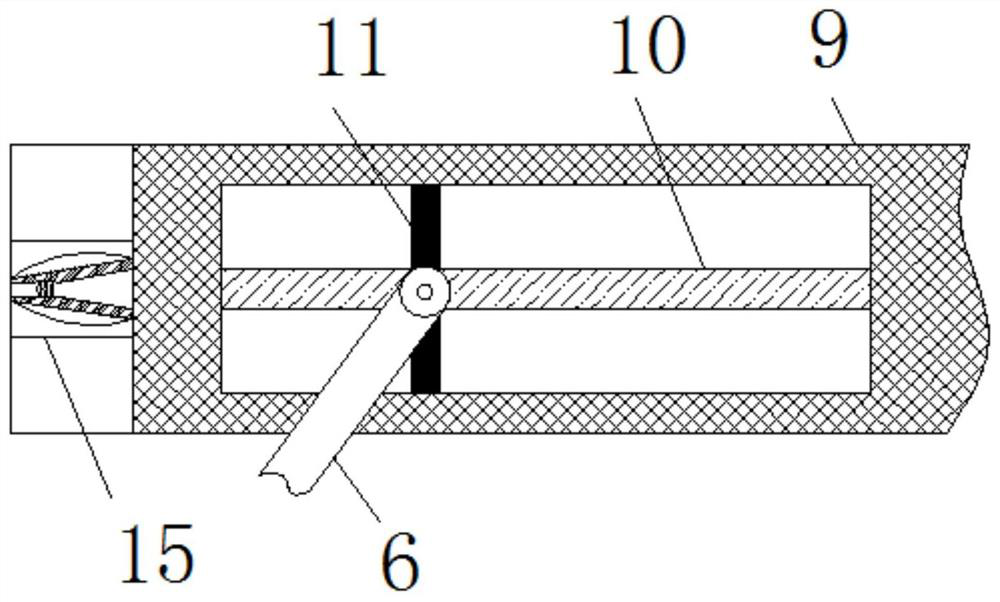
[0027] see Figure 1-4 , an injection mold device capable of discharging trapped gas during injection molding. The mold 1 is combined, and then the injection molding solution is injected from the injection port 2. When the solution enters the injection cavity, the high temperature will be transmitted to the ventilation device 9, and the gas in the ventilation device 9 will expand when heated, driving the sliding rod 11 to move on the fixed rod 10. Sliding on ...


PUM


Abstract

The invention relates to the technical field of injection molds, and discloses an injection mold device capable of discharging residual gas during injection molding. The injection mold device comprises a fixed mold, wherein an injection molding opening is formed in the upper end of the fixed mold, a movable mold is movably installed at the lower end of the fixed mold, movable grooves are formed inthe left end and the right end of the movable mold, connecting rods are movably hinged to the left end and the right end of the movable mold, guide rods are movably installed on the opposite surfacesof the connecting rods, and reset springs are fixedly installed between the connecting rods and the movable mold. According to the injection mold device capable of discharging the residual gas duringinjection molding, the movable mold is used for carrying out mold closing on the fixed mold, then an injection molding solution is injected from the injection molding opening, when the solution enters an injection molding cavity, high temperature can be conducted into an air exchange device, gas in the air exchange device is heated to expand, a sliding rod is driven to slide on a fixing rod, so that the guide rods are matched to drive the connecting rods to rotate towards the two sides, and the effect that the movable mold and a mold core are more tightly combined is achieved.

Description

technical field [0001] The invention relates to the technical field of injection molds, in particular to an injection mold device capable of discharging trapped gas during injection molding. Background technique [0002] Injection molding, also known as injection molding, is a method of injection and mold molding. The advantages of injection molding are fast production speed, high efficiency, and automatic operation, which brings great convenience to industrial production. The processing of the shape of the article is mainly achieved through the change of the physical state of the formed material, which is called the "mother of industry". [0003] In the injection molding process of existing injection molds, when the plastic melt passes through the runner, the plastic melt is generally injected directly through the main channel and the runner. In the process, a huge pressure is formed on the injection cavity, which leads to the imprinted constant base on the product after t...

Claims


Application Information

Patent Timeline
Patent Type & Authority Applications(China)
IPC IPC(8): B29C45/34B29C45/26B29C45/73B29C45/40
CPCB29C45/2608B29C45/34B29C45/401B29C45/7337
Inventor 周磊
Owner 周磊
Learn More