
Bone cement system

a cement system and cement technology, applied in the field of bone cement systems, can solve the problems of empty space, and inability to complete monomer transfer from the monomer reservoir container into the cement powder

Active Publication Date: 2012-02-02
HERAEUS MEDICAL
View PDF3 Cites 12 Cited by
  • Summary
  • Abstract
  • Description
  • Claims
  • Application Information

AI Technical Summary

Benefits of technology

The invention is a bone cement system that is protected against clogging and incomplete monomer transfer. It allows for the injection of monomer liquid into cement powder without sticking or incomplete transfer. The system includes a dispensing opening with a shield and a ratio of area to sieve opening of at least 1 to 3. A vacuum is applied opposite the dispensing opening to generate a negative pressure in the feed opening, which removes residual air and monomer liquid from the system. The sieve element separates the conveyor and the mixing cylinder, preventing cement powder from flowing into the conveyor. The system also allows for the dispensing of bone cement mixed from the cement powder and monomer liquid. The sieve element has a mesh size of less than -30 μm to prevent the flow of cement powder and facilitate the flow of monomer liquid. Overall, the system ensures complete monomer transfer and prevents clogging, resulting in improved mechanical properties of the bone cement.

Problems solved by technology

The bone cement system must not get sticky, since this renders complete monomer transfer from the monomer reservoir container into the cement powder impossible.
As a result, the intervening space no longer contains cement powder and is empty.

Method used


Image

  • Bone cement system
  • Bone cement system
  • Bone cement system

Examples


Embodiment Construction

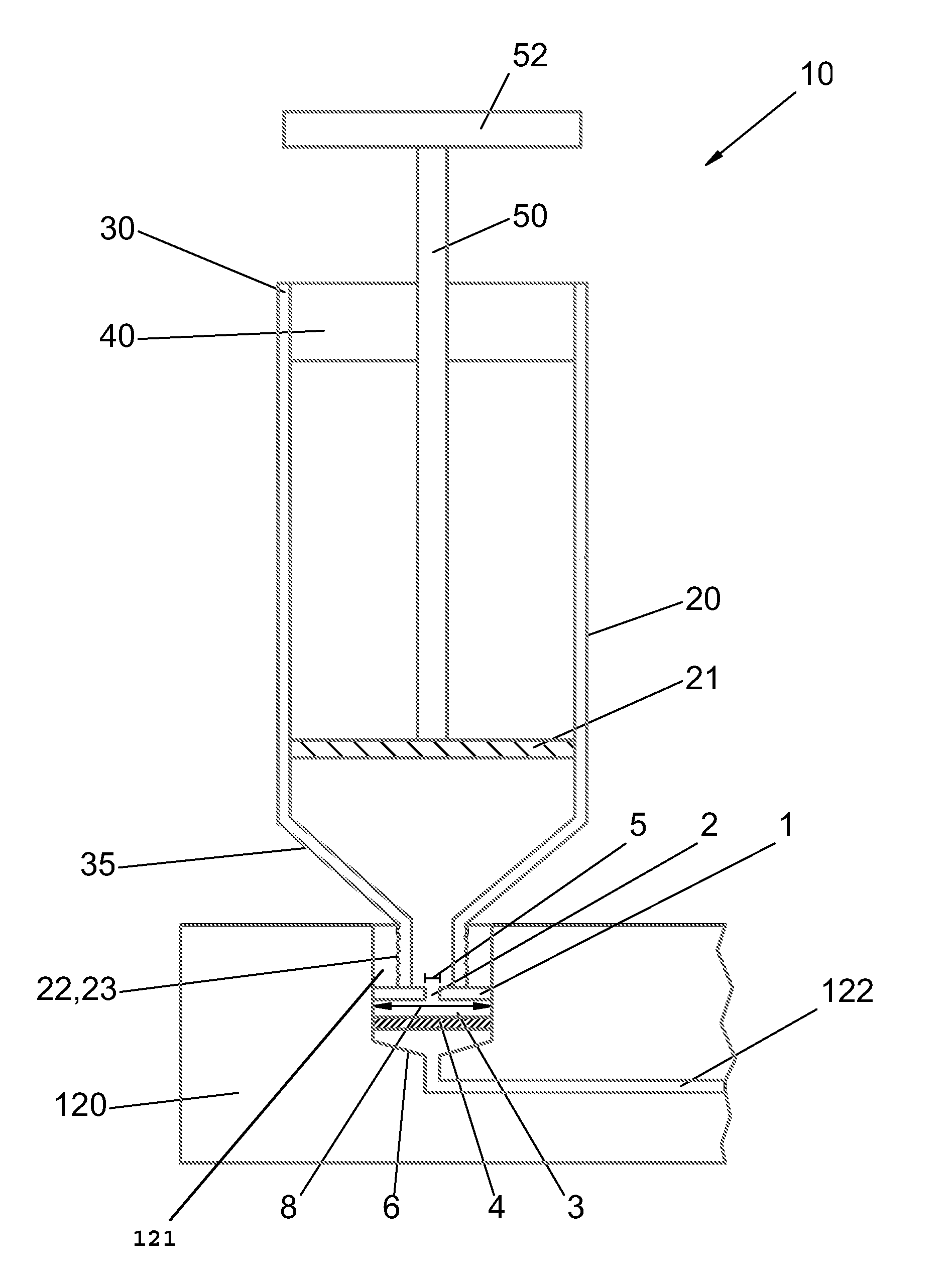
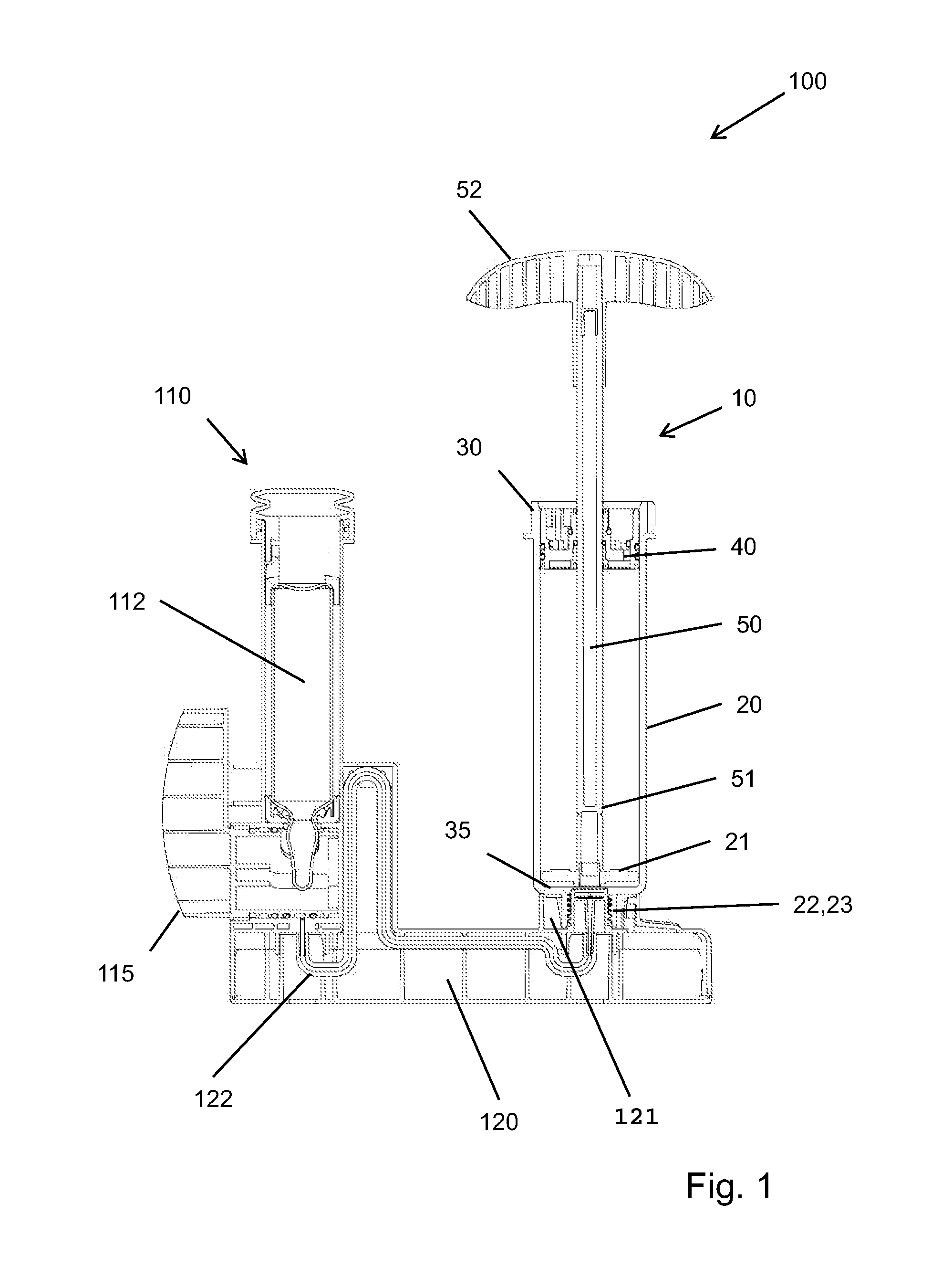
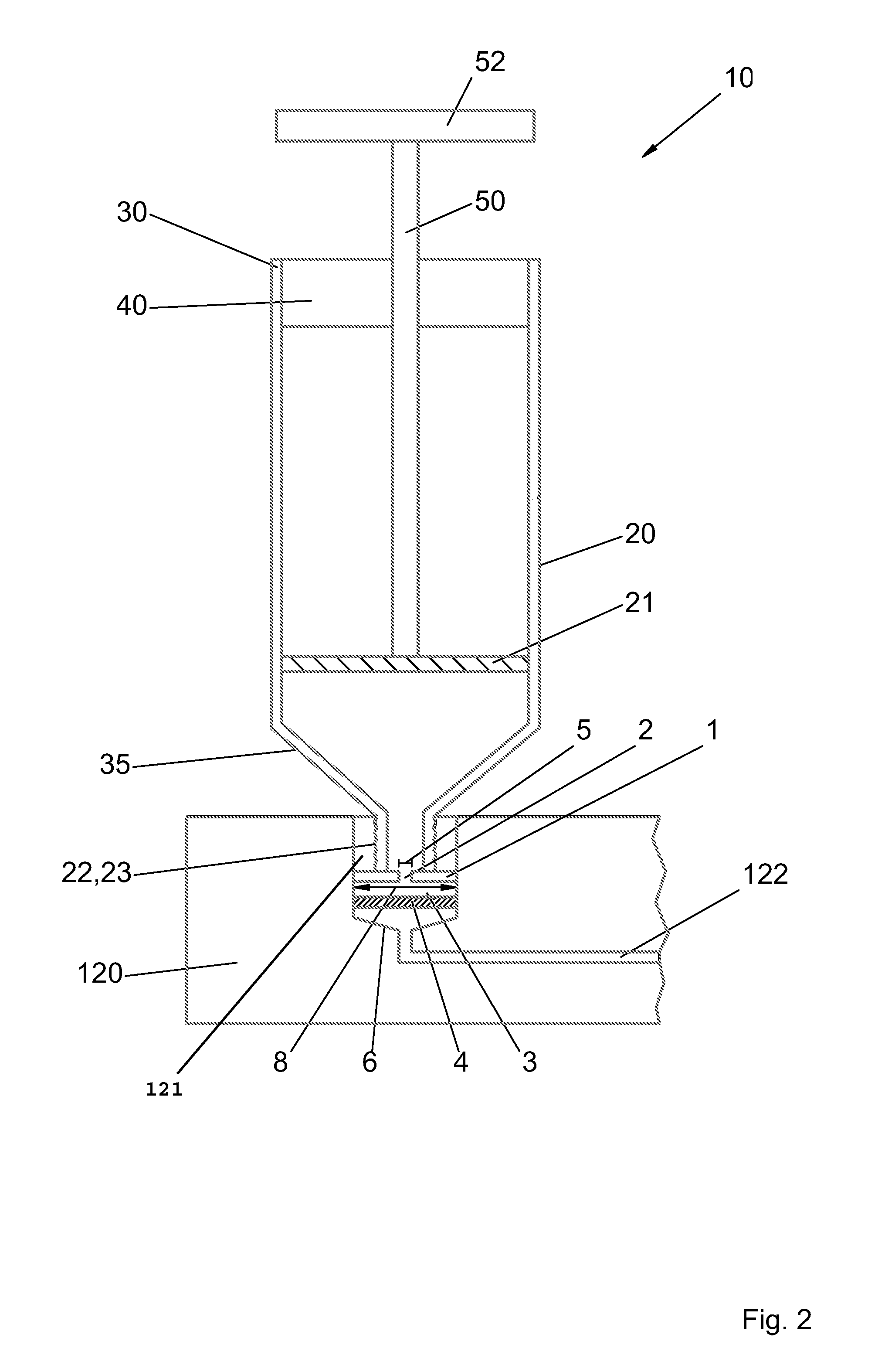
[0030]FIG. 1 shows a bone cement system 100 according to an embodiment of the invention. The bone cement system 100 comprises a mixing facility 10 for mixing and dispensing bone cement. The mixing facility 10 is stored on a base 120 in the exemplary embodiment shown. The base 120 also carries a reservoir facility 110 for a monomer. The bone cement system 100 serves for mixing the bone cement. For this purpose, bone cement powder is filled into a mixing cylinder 20 of the mixing facility 10. The bone cement powder can subsequently be mixed with the monomer in order to form bone cement. As illustrated in FIG. 1, reservoir facility 110 is part of the bone cement system 100. Reservoir facility 110 stores a reservoir container 112 for the monomer.

[0031]An outflow of the monomer from the reservoir container 112 can be controlled and / or triggered via a valve 115. Advantageously, the reservoir container 112 is a glass container that is opened in its head region by the valve 115. The monomer...


PUM

PropertyMeasurementUnit
distanceaaaaaaaaaa
distanceaaaaaaaaaa
distanceaaaaaaaaaa

Abstract

A bone cement system (100) is provided having a mixing facility (10) for mixing and dispensing of bone cement, a reservoir container (112) for a monomer, and a conveyor (122). The mixing facility (10) has a mixing cylinder (20), which stores a bone cement powder. The monomer can be conveyed from the reservoir container (112) into the mixing cylinder (20) by the conveyor (122). A sieve element is (4) is arranged between the reservoir container (112) and the mixing facility (10), in order to preventingress of the bone cement powder from the mixing cylinder (20) into the conveyor (122). The mixing device (10) included a dispensing opening (23) for dispensing a bone cement mixed from the bone cement powder and the monomer. The dispensing opening (23) includes a shield (1) having at least one through-opening (2). The ratio of the area of the through-opening (2) to the area of the sieve element (4) is at least 1 to 3, and the distance between the shield (1) and the sieve element (4) is at least 1 mm.

Description

BACKGROUND OF THE INVENTION[0001]The invention relates to a bone cement system having a mixing facility for the mixing and dispensing of bone cement, a reservoir container for a monomer, and a conveyor, wherein the mixing facility comprises a mixing cylinder, the mixing cylinder stores a bone cement powder, the monomer can be conveyed from the reservoir container into the mixing cylinder by the conveyor, a sieve element is arranged between the reservoir container and the mixing facility to prevent the ingress of the bone cement powder from the mixing cylinder into the conveyor, and the mixing facility comprises a dispensing opening for dispensing a bone cement obtained by mixing the bone cement powder and the monomer.[0002]PMMA bone cements have been known for decades and are based on the groundbreaking work of Sir Charnley (Charnley, J., “Anchorage of the femoral head prosthesis of the shaft of the femur,”J. Bone Joint Surg. 42: 28-30 (1960)). The basic structure of PMMA bone cemen...

Claims


Application Information

Patent Timeline
Patent Type & Authority Applications(United States)
IPC IPC(8): B01F5/06B01F15/02
CPCA61B17/8833B01F2215/0029B01F13/003B01F3/2057A61B17/8827B01F23/708B01F33/5012B01F2101/20
Inventor VOGT, SEBASTIANSTOCKLI, ROCHUSBUCHNER, HUBERT
Owner HERAEUS MEDICAL
Learn More