Driving device of UV lamp tube and driving method thereof

A driving device and lamp technology, applied in the direction of electrical components, etc., can solve problems such as difficult lamp frequency and lamp current control, increase product scrap rate and detection matching process test cycle, affect lamp brightness, etc., to prevent dimming or even failure in the later stage Brightness, avoid battery voltage drop, and prolong service life

Pending Publication Date: 2020-10-02
广东省闪耀科技开发有限公司
View PDF0 Cites 0 Cited by
  • Summary
  • Abstract
  • Description
  • Claims
  • Application Information

AI Technical Summary

Problems solved by technology

Due to the limitation of the production process of UV lamp tubes, the consistency of the starting voltage of UV lamp tubes varies greatly during mass production.
[0003] At present, UV lamps generally use traditional Royer topology UV drive circuits. This Royer topology UV drive circuit is a self-oscillating structure. Due to its simple structure, mature technology, and price advantages, it is widely used; Due to the influence of parameter deviation, it is difficult to achieve strict lamp frequency and lamp current control, both of which will affect the brightness of the lamp. Moreover, when the Royer topology UV drive circuit is used to match the lamp tube, it is easy to have a low matching degree, resulting in inaccurate The increase of good products increases the product scrap rate and the test cycle of the detection matching process

Method used


Image

  • Driving device of UV lamp tube and driving method thereof
  • Driving device of UV lamp tube and driving method thereof
  • Driving device of UV lamp tube and driving method thereof

Examples


Embodiment Construction

[0022] The present invention will be further described below in conjunction with the accompanying drawings and embodiments.

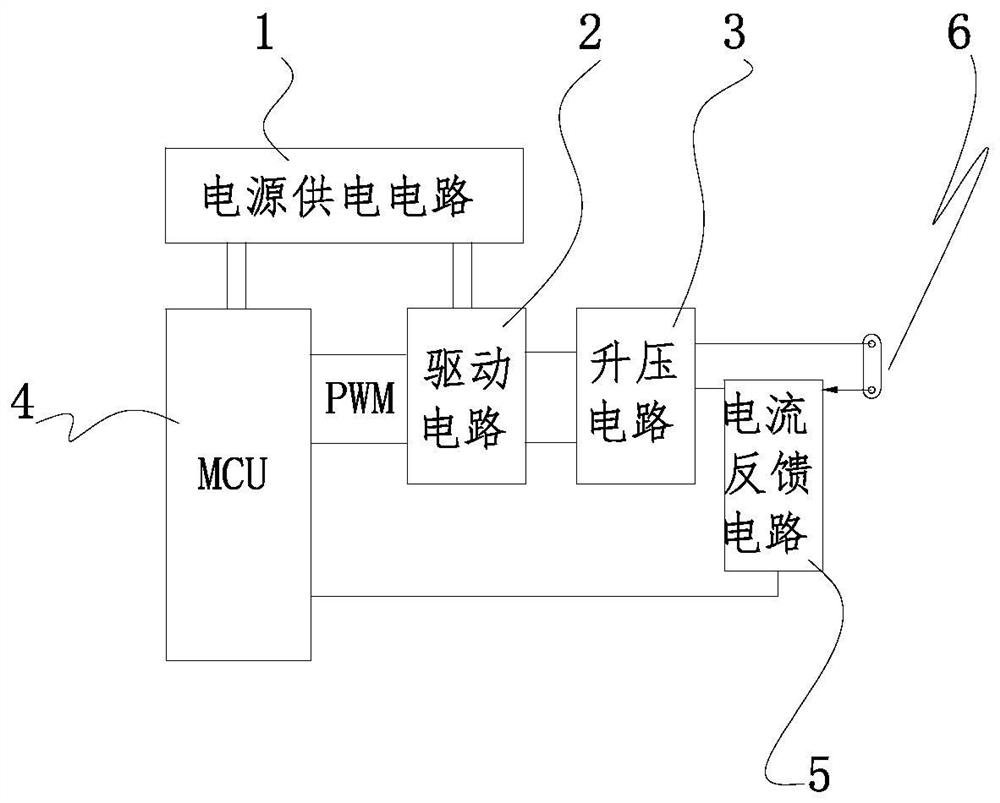
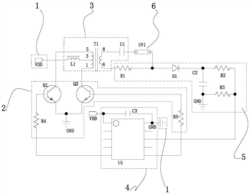
[0023] see Figure 1-Figure 2 , the driving device of the UV lamp includes a power supply circuit 1, a drive circuit 2, a boost circuit 3 and a UV lamp 6, and also includes a current feedback circuit 5 and an MCU single-chip microcomputer 4, wherein the power supply circuit 1 is connected to the MCU main The control circuit 4 is electrically connected with the drive circuit 2, and the MCU single-chip microcomputer 4, the drive circuit 2, and the booster circuit 3 are electrically connected in turn and connected with one end of the UV lamp 6, and the other end of the UV lamp 6 is connected to the booster through the current feedback circuit 5. The piezoelectric circuit 3 is electrically connected.

[0024] In this embodiment, the power supply circuit 1 is a battery-powered power supply circuit.

[0025] The battery is a primary battery or a secondary b...


PUM


Abstract

The invention discloses a driving device of a UV lamp tube and a driving method thereof. The driving device of the UV lamp tube comprises a power supply circuit, a driving circuit, a boosted circuit and the UV lamp tube; the device is characterized in that the device also comprises a current feedback circuit and an MCU single-chip microcomputer, wherein the power supply circuit is electrically connected with the MCU main control circuit and the driving circuit respectively; the MCU single-chip microcomputer, the driving circuit and the boosted circuit are electrically connected in sequence andthen are connected with one end of the UV lamp tube; and the other end of the UV lamp tube is electrically connected with the boosted circuit through the current feedback circuit. The operation method of the driving device of the UV lamp tube comprises the following steps: 1, driving a first triode Q1 and a second triode Q2 through a PWM port of the MCU single-chip microcomputer every time when the transformer T1 is powered on and started, so that the first triode Q1 and the second triode Q2 are conducted in turn, and high-voltage sine waves are generated at the secondary side of the transformer T1 and are coupled through a first capacitor C1. The device has the characteristic of long service life.

Description

technical field [0001] The invention relates to a driving device for a UV lamp tube and a driving method thereof. Background technique [0002] UV lamps are commonly used disinfection devices, and are widely used in various health disinfection industries such as life and medical treatment. Due to the limitation of the production process of UV lamp tubes, the consistency of the ignition voltage of UV lamp tubes varies greatly during mass production. [0003] At present, UV lamps generally use traditional Royer topology UV drive circuits. This Royer topology UV drive circuit is a self-oscillating structure. Due to its simple structure, mature technology, and price advantages, it is widely used; Due to the influence of parameter deviation, it is difficult to achieve strict lamp frequency and lamp current control, both of which will affect the brightness of the lamp. Moreover, when the Royer topology UV drive circuit is used to match the lamp tube, it is easy to have a low matc...

Claims


Application Information

Patent Timeline
IPC IPC(8): H05B47/10
CPCH05B47/10
Inventor 胡红斌
Owner 广东省闪耀科技开发有限公司
Why Eureka
Try Eureka