
Ohm voltage drop automatic compensation rapid scanning circuit based on solution resistance measurement

A solution resistance and measurement circuit technology, which is applied in the direction of fluid resistance measurement, adjustment of electrical variables, and material electrochemical variables, can solve the problems of inconsistent frequency, self-excited oscillation of the circuit, and low accuracy, and achieve overcompensation and accuracy High, easy-to-operate effect

Active Publication Date: 2020-10-02
NINGBO UNIV
View PDF5 Cites 5 Cited by
  • Summary
  • Abstract
  • Description
  • Claims
  • Application Information

AI Technical Summary

Problems solved by technology

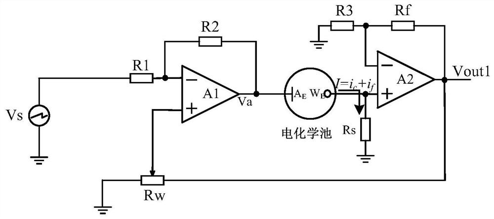
The fast scanning circuit with automatic ohmic voltage drop compensation function realizes automatic compensation and overcomes the defect of manual compensation of the dual operational amplifier fast scanning circuit in Document 1, but the frequency detection circuit judges the frequency based on the occurrence of serious overcompensation , the circuit will have self-excited oscillation, making the frequencies of fx1 and fx2 inconsistent. If it is only a slight overcompensation, the circuit will not have self-excited oscillation, so the fast scan circuit with automatic compensation function for ohmic voltage drop still has overcompensation problem, the accuracy is still not high

Method used


Image

  • Ohm voltage drop automatic compensation rapid scanning circuit based on solution resistance measurement
  • Ohm voltage drop automatic compensation rapid scanning circuit based on solution resistance measurement
  • Ohm voltage drop automatic compensation rapid scanning circuit based on solution resistance measurement

Examples


Embodiment

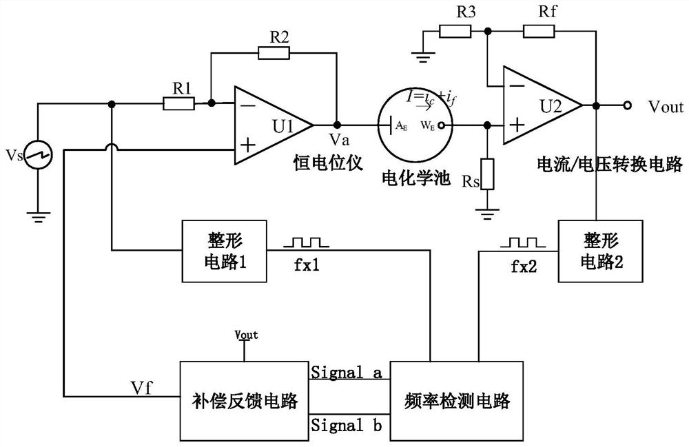
[0024] Example: such as image 3 As shown, a fast scanning circuit for automatic compensation of ohmic voltage drop based on solution resistance measurement, including a potentiostat, a current / voltage conversion circuit and a digital potentiometer, the digital potentiometer is used to generate a compensation voltage signal V f , the potentiostat is used to access the scanning voltage signal Vs provided by the AC power supply, and combine the scanning voltage signal Vs with the compensation voltage signal V output by the digital potentiometer f After being superimposed, it acts on the electrochemical cell, so that the current signal I generated in the electrochemical cell is output on its working electrode. The current / voltage conversion circuit is used to convert the current signal I generated in the electrochemical cell into a voltage signal output, and the ohmic voltage drop is automatically compensated. The fast scanning circuit also includes an amplifying circuit, a first...


PUM


Abstract

The invention discloses an ohm voltage drop automatic compensation rapid scanning circuit based on solution resistance measurement. The circuit comprises a potentiostat, a current / voltage conversion circuit, a digital potentiometer, an amplifying circuit, a first electronic switch, a second electronic switch, a solution resistance measuring circuit and a microcontroller. The microcontroller controls the switching-on of the first electronic switch and the second electronic switch; a solution resistance measuring circuit measures and obtains equivalent resistance in an electrochemical cell; thesolution resistance measuring circuit transmits the obtained equivalent resistance to the microcontroller; the microcontroller calculates a tap coefficient of the digital potentiometer based on the equivalent resistance of the solution; a tap position of the digital potentiometer is adjusted according to the tap coefficient, so the digital potentiometer outputs a feedback voltage signal matched with the tap coefficient; the potentiostat superposes the feedback voltage signal and the scanning voltage signal and then acts on the electrochemical cell, and therefore, the ohmic voltage drop automatic compensation is realized. The circuit has the advantages of no overcompensation problem and higher accuracy on the basis of simplicity and convenience in operation.

Description

technical field [0001] The invention relates to an ohmic voltage drop automatic compensation fast scanning circuit, in particular to an ohmic voltage drop automatic compensation fast scanning circuit based on solution resistance measurement. Background technique [0002] Cyclic voltammetry is one of the most important electrochemical research methods at present. Cyclic voltammetry changes the scanning rate of the electrode potential to cause oxidation and reduction reactions to alternately occur on the electrode, and records the current-potential curve (voltammetry curve). The reversibility of the electrode reaction can be judged according to the shape of the current-potential curve. Cyclic voltammetry has been widely used to study the nature, mechanism and kinetic parameters of electrode reactions. However, as the scanning rate of the electrode potential increases, the distortion of the volt-ampere characteristic curve caused by the ohmic voltage drop of the solution becom...

Claims


Application Information

Patent Timeline
IPC IPC(8): G05F1/56G01N27/48G01R27/22
CPCG01N27/48G01R27/22G05F1/561
Inventor 肖凤明邬杨波胡振德谢建军郭智勇
Owner NINGBO UNIV
Learn More