
Electric power steering pipe column sub-assembly snap spring embedding mechanism

A steering column and electric power assist technology, applied in hand-held tools, manufacturing tools, etc., can solve problems such as limited pressure, unreliable bearing installation, and affecting the quality of the steering column, and achieve the effect of improving efficiency and quality

Pending Publication Date: 2020-10-02
GUANGDONG HESHI AUTOMATION TECH CO LTD
View PDF0 Cites 0 Cited by
  • Summary
  • Abstract
  • Description
  • Claims
  • Application Information

AI Technical Summary

Problems solved by technology

[0003] In the prior art, when assembling the steering column, the steering column sub-assembly is first assembled, that is, the protective tube assembly, the steering shaft, the booster shaft and the housing are assembled together, and then inserted into the steering shaft in sequence. Bearings and circlips, and forcefully press the circlips to the set position on the inner wall of the upper protective tube. During this process, workers cannot position the steering column sub-assembly, so it is extremely inconvenient to apply pressure on the circlips, and The pressure exerted by the workers is limited, and often the circlip cannot be pressed into the set position, and the installation of the bearing is unreliable. During use, the bearing is prone to loosening, which affects the quality of the steering column

Method used


Image

  • Electric power steering pipe column sub-assembly snap spring embedding mechanism
  • Electric power steering pipe column sub-assembly snap spring embedding mechanism
  • Electric power steering pipe column sub-assembly snap spring embedding mechanism

Examples


Embodiment Construction

[0027] Embodiments of the present invention are described in detail below, examples of which are shown in the drawings, wherein the same or similar reference numerals designate the same or similar elements or elements having the same or similar functions throughout. The embodiments described below by referring to the figures are exemplary only for explaining the present invention and should not be construed as limiting the present invention.

[0028] In the description of the present invention, it should be understood that the orientation descriptions, such as up, down, front, back, left, right, etc. indicated orientations or positional relationships are based on the orientations or positional relationships shown in the drawings, and are only In order to facilitate the description of the present invention and simplify the description, it does not indicate or imply that the device or element referred to must have a specific orientation, be constructed and operated in a specific ...


PUM


Abstract

The invention discloses an electric power steering pipe column sub-assembly snap spring embedding mechanism comprising a machine frame, a positioning clamping assembly, a baffle and an upward pullingassembly. The positioning clamping assembly comprises a first clamping piece, a second clamping piece and blocking hooks which are sequentially arranged from bottom to top, and the two blocking hooksare horizontally arranged. A stop piece is installed on the lower side of the baffle. A first vertical through hole is formed in the stop piece. The upward pulling assembly comprises a connector. Theblocking hooks penetrate through horizontal through holes and can stop locking blocks. The lower end of an assistance shaft is clamped by the first clamping piece, a lower protection pipe is clamped by the second clamping piece, and a steering pipe column sub-assembly is positioned and installed on the positioning clamping assembly. When the steering pipe column sub-assembly slides upwards, a steering shaft penetrates through the first vertical through hole. The connector rotates around the axis of itself so as to be connected with the steering shaft in a threaded manner, then the steering pipe column sub-assembly is driven to move upwards together, a snap spring is embedded in the steering pipe column sub-assembly after being stopped, and therefore a bearing can be effectively clamped, and the quality of steering pipe columns is improved.

Description

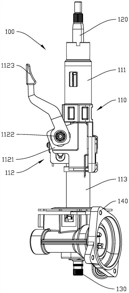
technical field [0001] The invention relates to the field of electric power steering systems, in particular to an electric power steering pipe column subassembly clip spring embedding mechanism. Background technique [0002] The steering column is an important part of the electric power steering system, which can transmit the force received by the steering wheel to the wheels through the steering gear. figure 1 It is a schematic diagram of the structure of the steering column. The steering column includes a protective tube assembly, a steering shaft, a booster shaft, and a housing. The booster shaft is installed on the housing. The upper end of the steering shaft passes through the upper end of the protective pipe assembly, and the lower end of the power assist shaft passes through the lower end of the housing. The protective tube assembly includes an upper protective tube, a locking assembly and a lower protective tube. The lower protective tube is fixedly installed on the...

Claims


Application Information

Patent Timeline
Patent Type & Authority Applications(China)
IPC IPC(8): B25B27/00B25B27/30
CPCB25B27/00B25B27/0035B25B27/30
Inventor 李卫彤陈荣张云彦吴少威
Owner GUANGDONG HESHI AUTOMATION TECH CO LTD
Learn More