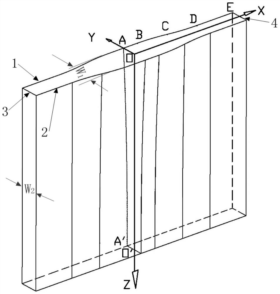
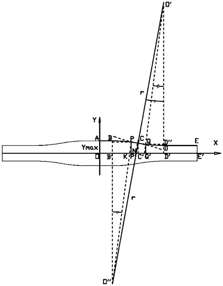
A crystallizer cavity structure

A mold and cavity technology, applied in the field of metal continuous casting, can solve the problem of large strain rate of thin slab billet shell, and achieve the effects of improving the quality of the billet, reducing the strain and alleviating stress concentration.

Active Publication Date: 2021-09-07
CISDI ENG CO LTD +1
View PDF2 Cites 0 Cited by
  • Summary
  • Abstract
  • Description
  • Claims
  • Application Information

AI Technical Summary

Problems solved by technology

[0008] In view of this, the object of the present invention is to provide a mold cavity structure based on continuous straightening curves to overcome the problem of excessive strain rate of the thin slab shell in the mold

Method used


Image

  • A crystallizer cavity structure
  • A crystallizer cavity structure
  • A crystallizer cavity structure

Examples


Embodiment Construction

[0040] Embodiments of the present invention are described below through specific examples, and those skilled in the art can easily understand other advantages and effects of the present invention from the content disclosed in this specification. The present invention can also be implemented or applied through other different specific implementation modes, and various modifications or changes can be made to the details in this specification based on different viewpoints and applications without departing from the spirit of the present invention. It should be noted that the diagrams provided in the following embodiments are only schematically illustrating the basic concept of the present invention, and the following embodiments and the features in the embodiments can be combined with each other in the case of no conflict.

[0041] Wherein, the accompanying drawings are for illustrative purposes only, and represent only schematic diagrams, rather than physical drawings, and should...


PUM


Abstract

The invention relates to a crystallizer cavity structure, which belongs to the field of metal continuous casting. The cavity-shaped structure is surrounded by four copper plates to form a tube, of which two copper plates facing each other are wide panels, and the other two facing copper plates are narrow panels; the wide panel is a curved panel; along the casting direction of the crystallizer, the curved panel The surface of the curved plate changes in a continuous straightening curve; along the horizontal direction of the crystallizer, the surface of the curved plate changes in a segmented function curve. By applying a continuous straightening curve, the curvature of the mold at its entrance is not 0, and within the limited length of the mold, the overall strain of the slab shell is small and constant, and the strain rate is low, which improves the quality of the slab; overcomes the The problem of excessive strain rate of the slab shell of the traditional thin slab mold in the mold improves the crack defect on the surface of the slab, reduces the wear of the slab to the copper plate coating of the mold, and prolongs the service life of the mold.

Description

technical field [0001] The invention belongs to the field of metal continuous casting, and in particular relates to a crystallizer cavity structure. Background technique [0002] The thin slab continuous casting and rolling process has the advantages of simplified process, short production process, less equipment, energy saving, high yield, etc., and can face the market more flexibly, and has become the key investment target of steel production companies in recent years. The main difference between thin slab continuous casting and rolling technology and conventional continuous casting technology lies in the mold. As we all know, in order to solve the problem of molten steel flow in the gap between the mold and the nozzle, the mold is designed in a funnel shape with a large top and a small bottom, but this design makes the billet shell subject to additional stress in the mold and is prone to crack defects. Therefore, the cavity shape curve of the mold is particularly importa...

Claims


Application Information

Patent Timeline
Patent Type & Authority Patents(China)
IPC IPC(8): B22D11/04
CPCB22D11/0406B22D11/0408
Inventor 刘强韩志伟邓比涛孔意文
Owner CISDI ENG CO LTD
Why Eureka
Try Eureka