
Multifunctional rehabilitation training device for endoneurology department

A neurology and rehabilitation training technology, applied in the field of medical rehabilitation training equipment, can solve the problems of insufficient nursing staff, single training method, and high cost of professional escort training, and achieve a convenient self-control strength, meet training needs, and improve comfort. Effect

Inactive Publication Date: 2020-10-02
徐强
View PDF0 Cites 5 Cited by
  • Summary
  • Abstract
  • Description
  • Claims
  • Application Information

AI Technical Summary

Problems solved by technology

[0003] In the existing medical rehabilitation training, most of them are accompanied or assisted by professional nursing staff. First, there is a problem of insufficient nursing staff. Second, there is a problem of high cost of professional escort training. Most patients will train at home by themselves.
When training at home, in order to ensure the training effect, it is necessary to be equipped with corresponding rehabilitation training equipment. However, most of the existing rehabilitation training equipment in the market has the problems of single training method and insufficient training effect; It is difficult to accurately control the training intensity, the comfort is poor, and the cost is high

Method used


Image

  • Multifunctional rehabilitation training device for endoneurology department
  • Multifunctional rehabilitation training device for endoneurology department
  • Multifunctional rehabilitation training device for endoneurology department

Examples


no. 1 example

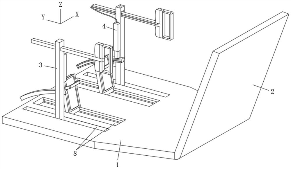
[0038] In this embodiment, the training mode in which the foot-lifting pedal 5 swings around the X-axis specifically realizes the forward and backward swing training of the trainer's ankle joint during the swing process.

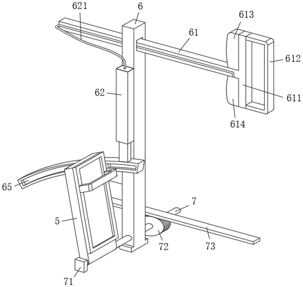
[0039] In this example, please continue to Figure 2-Figure 6 As shown, the driving mechanism that drives the pedal 5 to swing around the X axis includes:

[0040] figure 2 and Figure 6 Among them, the handle bar 61 that runs through the column 6 and can move back and forth in the column 6, a handle is installed on the end of the handle bar 61 close to the backrest 2, and the limit tooth plate 615 is embedded in the handle bar 61;

[0041] figure 2 Among them, the rotating shaft 7 that runs through the bottom end of the pedal 5 and the bottom end of the column 6; specifically regarding the cooperation of the rotating shaft 7 with the pedal 5 and the column 6, it is preferably: the rotating shaft 7 and the column 6 are rotatably matched, and the rotatin...

no. 2 example

[0049] On the basis of the structure of the first embodiment, the present embodiment provides a training mode in which the pedal 5 reciprocates along the Y-axis direction, and realizes the training of the trainer's thigh (root) joint and knee joint during the movement.

[0050] In this example, see figure 2 As shown, the handle mounted on one end of the handle bar 61 includes a mounting plate 611, the mounting plate 611 and the handle bar 61 are combined into a T-shaped structure, and a pull ring 612 is installed on one side of the mounting plate 611, and an air bag is installed on the other side. Used to define the Z-axis position of the limiting tooth plate 615;

[0051] Further, combine Figure 4 As shown, the limit tooth plate 615 includes the highest position and the lowest position on the Z axis; when the limit tooth plate 615 is at the lowest position, the handle rod 61 drives the pedal 5 to rotate around the X axis; the limit tooth plate 615 is at the highest positio...

no. 3 example

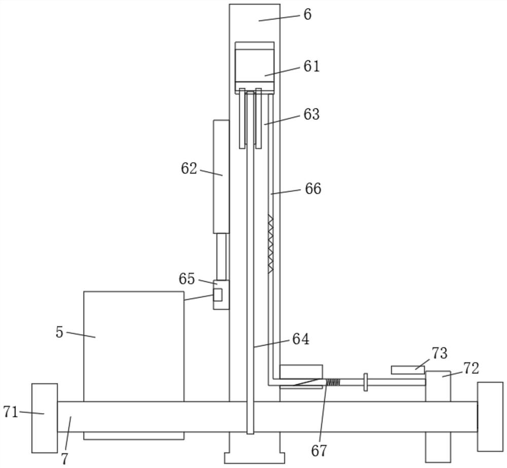
[0063] This embodiment is a further preferred embodiment of the second embodiment. In this embodiment, please refer to figure 2 and image 3 As shown, a movable gear 72 is sleeved on the rotating shaft 7, and one end of the cross bar 67 of the gear 72 is rotationally connected, and a rack 73 is provided inside the base 1, and the rack 73 and the gear 72 are meshed with each other to limit the foot. When the pedal 5 moves along the Y axis, it swings around the X axis synchronously.

[0064] Based on the traverse reset of the crossbar 67 in the above-mentioned second embodiment, it will drive the gear 72 to move to the left ( image 3 view), at this time, the gear 72 is gradually meshed with the rack 73, thereby realizing the following drive:

[0065] exist figure 2 and image 3 Among them, the rack 73 meshes with the top of the gear 72, so it can be seen that when the rotating shaft 7 moves with the pedal 5 (closer to the backrest 2), the rack 73 meshes with the gear 72, ...


PUM


Abstract

The invention belongs to the technical field of medical rehabilitation training instruments, and discloses a multifunctional rehabilitation training device for the endoneurology department. The devicecomprises a base; the top of the base is divided into a seat area and a structure mounting area; a left limb training device and a right limb training device are symmetrically mounted in the structure mounting area; the left limb training device and the right limb training device each comprise a sliding groove formed in the top of the structure mounting area and are slidably connected with a pedal and a stand column through the sliding grooves; the pedal is used for fixing the feet of the trainee, can reciprocate in the Y-axis direction along the sliding groove and can swing around the X axisand the Y axis in a reciprocating mode; and a driving mechanism is installed on the stand column and used for driving the pedal to move or swing. In conclusion, thigh joints and knee joints can be effectively trained through movement of the pedal, ankle joints can be trained in a multi-degree-of-freedom mode through swinging of the pedal, multiple purposes are achieved through one machine, and therefore the whole device can meet different use requirements.

Description

technical field [0001] The invention belongs to the technical field of medical rehabilitation training equipment, and in particular relates to a multifunctional rehabilitation training device for neurology departments. Background technique [0002] At present, there are a large number of patients with cardiovascular and cerebrovascular diseases or nervous system diseases in the elderly population, and most of these patients are accompanied by symptoms of limb movement disorders such as hemiplegia. In addition, with the rapid development of modern traffic, there are more and more neurological injuries or limb injuries caused by traffic accidents. In medicine, for the above-mentioned patients with mobility impairment, in addition to surgical treatment, corresponding rehabilitation training should be combined to achieve a good recovery effect. [0003] In the existing medical rehabilitation training, most of the training is accompanied or assisted by professional nursing staff...

Claims


Application Information

Patent Timeline
IPC IPC(8): A63B23/12A63B22/04A61H1/02
CPCA61H1/0237A61H1/024A61H2201/1269A61H2201/1642A61H2201/1669A63B21/00178A63B22/04A63B23/12
Inventor 徐强
Owner 徐强
Learn More