
Light guide plate photoetching equipment

A technology of lithography equipment and light guide plate, applied in microlithography exposure equipment, optomechanical equipment, optics, etc., can solve the problems of non-vertical, eccentric beam, affecting product quality, etc., and achieve the effect of improving quality

Pending Publication Date: 2020-09-29
SVG TECH GRP CO LTD
View PDF6 Cites 0 Cited by
  • Summary
  • Abstract
  • Description
  • Claims
  • Application Information

AI Technical Summary

Problems solved by technology

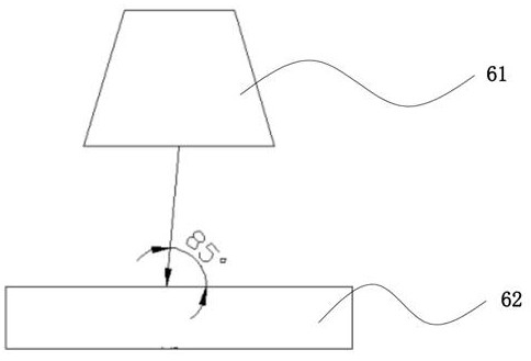
Products currently on the market, such as mobile phones, computers, televisions, and other electronic products that include displays, all have small-sized light guide plates. However, when making large-sized light guide plates, such as figure 1 As shown, when the engraving range of the laser exit field mirror 61 gradually increases from small to large at the same position, the light beam will be off-centered, so that the light beam is not perpendicular to the light guide plate placement platform 62, thereby affecting the quality of the light guide plate (making the dot shape Abnormal phenomenon occurs, which greatly affects the quality of the product), and also limits the efficiency of the operation

Method used


Image

  • Light guide plate photoetching equipment
  • Light guide plate photoetching equipment
  • Light guide plate photoetching equipment

Examples


Embodiment Construction

[0020] The specific embodiments of the present invention will be described in further detail below with reference to the accompanying drawings and embodiments. The following examples are intended to illustrate the present invention, but not to limit the scope of the present invention.

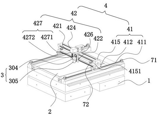
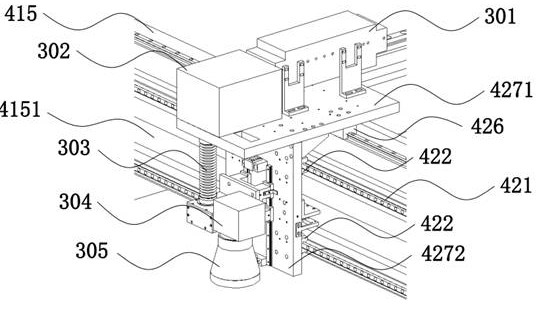
[0021] Please refer to figure 2 and image 3 , the light guide plate lithography apparatus provided in the embodiment of the present invention includes a base 1, a platform 2 arranged on the base 1 for placing the light guide plate and a lithography mechanism 3 for lithography The mechanism 3 moves relative to the platform 2 and the photolithography mechanism 3 uses a guide mechanism 4 for lithography that is always perpendicular to the platform 2 during movement. The guiding mechanism 4 is respectively connected to the photolithography mechanism 3 and the platform 2 . The guiding mechanism 4 includes a first guiding mechanism 41 for realizing the horizontal movement of the lithography mech...


PUM


Abstract

The invention discloses photoetching equipment for a light guide plate. The equipment comprises a base, a platform which is arranged on the base and is used for placing a light guide plate, a photoetching mechanism which is used for photoetching the light guide plate, and a guide mechanism which is used for realizing the movement of the photoetching mechanism relative to the platform, wherein a light beam, used for photoetching, of the photoetching mechanism is always vertical to the platform when the photoetching mechanism moves, the guide mechanism is respectively connected with the photoetching mechanism and the platform, and comprises a first guide mechanism for realizing the movement of the photoetching mechanism along a first direction and a second guide mechanism for realizing the movement of the photoetching mechanism along a second direction. Through the structure, the abnormal phenomenon of the lattice point morphology after photoetching is avoided, and the product quality isgreatly improved.

Description

technical field [0001] The invention relates to the technical field of light guide plate processing equipment, in particular to a light guide plate lithography equipment. Background technique [0002] The widespread use of liquid crystal displays has also prompted the rise of the light guide plate processing industry. At present, the light guide plates of products on the market, such as mobile phones, computers, TVs and other electronic products including displays, are of small size. figure 1 As shown in the figure, when the engraving range of the laser exit field mirror 61 gradually increases from small to large at the same position, the beam will be eccentric, so that the beam is not perpendicular to the light guide plate placement platform 62, thereby affecting the quality of the light guide plate (making the dot morphology Abnormal phenomena occur, which greatly affects the quality of the product), and also limits the improvement of the efficiency of the operation. [...

Claims


Application Information

Patent Timeline
Patent Type & Authority Applications(China)
IPC IPC(8): G03F7/00G03F7/20
CPCG03F7/0005G03F7/2053G03F7/2057
Inventor 张恒方宗豹浦东林陈林森
Owner SVG TECH GRP CO LTD
Learn More