Miniature head-mounted microscope
A head-mounted and microscope technology, applied in optics, instruments, radio wave measurement systems, etc., can solve the problems that the weight and volume of micro-probes cannot be further reduced, and the head-mounted microscope has a single function
- Summary
- Abstract
- Description
- Claims
- Application Information
AI Technical Summary
Problems solved by technology
Method used
Image


Examples
Embodiment 1
[0039] as attached figure 1 Shown:
[0040] Such as figure 1As shown, a miniature head-mounted microscope includes a micro probe and an imaging structure, the micro probe includes a housing 15, an objective lens 7, a scanner 14 and a collimator, and the housing 15 is a sealed structure of a polymer material, The volume of the housing 15 (that is, the entire micro-optical probe) is less than 5mm*5mm*5mm, here the volume is equal to 4mm*4mm*5mm; the objective lens 7 and the collimator are respectively fixed on the housing 15, and the housing 15 is also fixedly connected with a laser Input fiber 8, the laser input fiber 8 is a polarization maintaining fiber or photonic crystal fiber, the design wavelength is any wavelength between 700nm and 1600nm, the material of the laser input fiber 8 is optical glass, quartz, plastic or high molecular polymer, the laser input The optical fiber 8 is used to transmit the ultrafast laser pulse generated by the external excitation light source ...
Embodiment 2
[0049] Such as Figure 5 As shown, the difference between this embodiment and Embodiment 1 is that the outside of the driver 1 is rotated through the shaft hole to be provided with an angle adjuster 11, the angle adjuster 11 is a rectangular frame, and the first torsion beam 9 and the second torsion beam 10 are both passed through the shaft. The hole is rotatably connected to the angle adjuster 11, and the outer peripheral wall of the angle adjuster 11 is fixedly clamped with a first rotating shaft 12 and a second rotating shaft 13, and the first rotating shaft 12 and the second rotating shaft 13 are symmetrical about the center of the driver 1 , and the first rotation axis 12 is perpendicular to the axis of the first torsion beam 9 . Both the first rotating shaft 12 and the second rotating shaft 13 are rotatably connected to the housing 15 through shaft holes, thereby realizing the rotatable connection between the scanner 14 and the housing 15 . During use, the driver 1 can ...
Embodiment 3
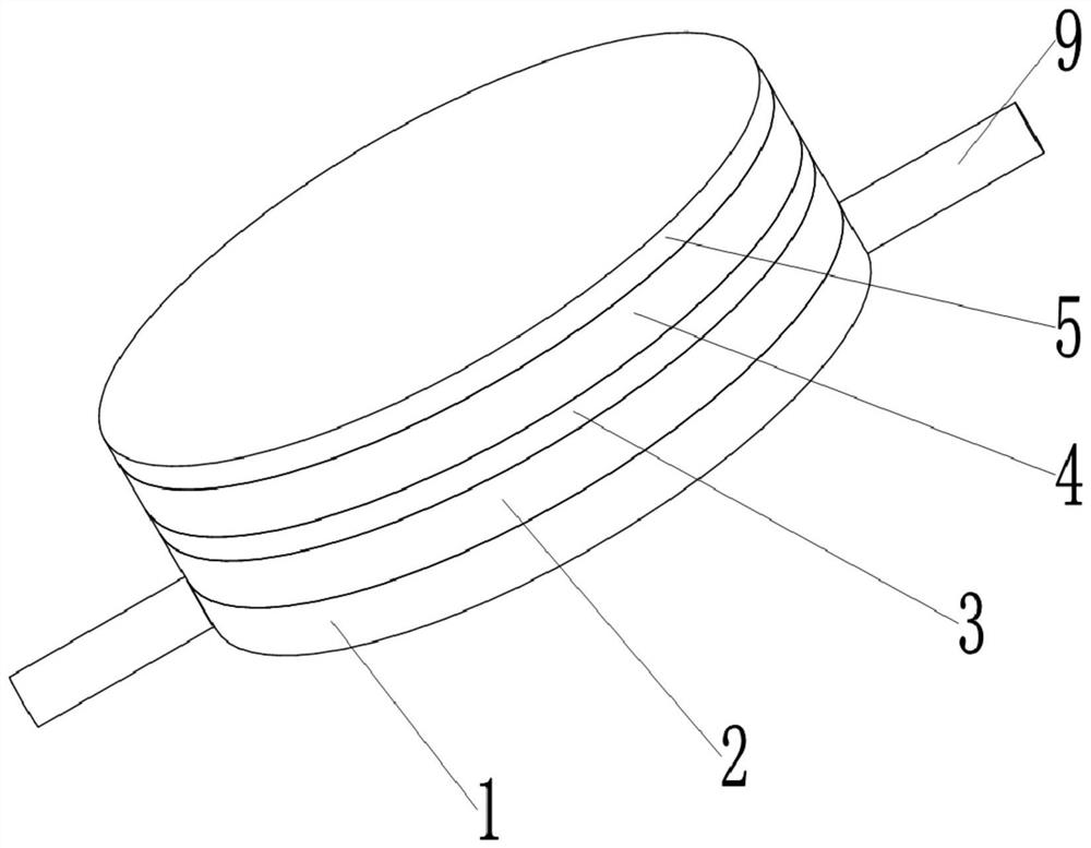
[0051] Such as Figure 6 As shown, the difference between the present embodiment and the first embodiment is that the driver 1 is a regular prism, and the mirror surfaces correspond to the sides of the driver 1 one by one. The driver 1 in this embodiment is in the shape of a regular hexagonal column, and the upper and lower ends of the driver 1 are coaxially fixed with torsion beams by bonding. The six side walls of the driver 1 are all fixed with mirrors by bonding. Wherein, the optical film adopts the filter film 4 and the polarization splitting film 5 .
[0052] This embodiment is applied to the case where the reflected light and the incident light of the miniature laser radar module waiting to detect the object 19 have the same wavelength, and the specific working process of the scanner 14 is as follows:
[0053] The scanner 14 is rotated by rotating the torsion beam, so as to achieve the purpose of adjusting the incident angle of the laser. Such as Figure 7 As shown,...
PUM
| Property | Measurement | Unit |
|---|---|---|
| transmittivity | aaaaa | aaaaa |
Abstract
Description
Claims
Application Information
 - R&D
- Intellectual Property
- Life Sciences
- Materials
- Tech Scout
- Unparalleled Data Quality
- Higher Quality Content
- 60% Fewer Hallucinations
Browse by: Latest US Patents, China's latest patents, Technical Efficacy Thesaurus, Application Domain, Technology Topic, Popular Technical Reports.
© 2025 PatSnap. All rights reserved.Legal|Privacy policy|Modern Slavery Act Transparency Statement|Sitemap|About US| Contact US: help@patsnap.com