Laser emitting coupling device and laser emitting and displaying coupling device, laser receiving coupling device and laser receiving and displaying coupling device and straight tube type double-tube distance measuring telescope

A coupling device and laser emission technology, applied in the direction of telescopes, optics, mirrors, etc., can solve the problems that affect the observation effect, the observation background cannot be color cast, and the body of the prism increases greatly, so as to ensure the observation brightness and observation effect. Effect

Pending Publication Date: 2020-09-29
上海龙达胜宝利光电有限公司
View PDF0 Cites 0 Cited by
  • Summary
  • Abstract
  • Description
  • Claims
  • Application Information

AI Technical Summary

Problems solved by technology

[0006] (2) Introduce the emitted and received laser light into the natural light path of the telescope, and the original technical indicators and observation effects of the telescope cannot be reduced, especially the observation brightness of the telescope cannot be reduced, and the observation background cannot be color cast
However, the conjugate moment of the object image at the introduction point is relatively large, resulting in a large size of the additional prism, resulting in a large increase in the body shape near the transfer prism, which may not be able to meet the requirement of a minimum eye distance of 55mm
[0010] (2) The reflection point 220b of the natural light at the exit surface of the roof prism in the relay prism 220 is used as the introduction point, which needs to be introduced with two prisms, and the operation is cumbersome; The distance, limited by the structure of the eyepiece group 230, will increase the body shape in the direction of the corresponding optical axis of the tilt, resulting in a large increase in the body shape of the lens barrel near the relay prism
[0011] (3) With the intersection 220c of the optical axis and the incident surface of the half pentaprism in the relay prism 220 as the introduction point, two prisms need to be used to introduce, compared with the above two introduction points, the object image at the introduction point The largest conjugate distance leads to the largest size of the introduced prism, resulting in a large increase in the body of the lens barrel near the relay prism, and may interfere with the focal plane of the corresponding objective lens group, affecting the observation effect

Method used


Image

  • Laser emitting coupling device and laser emitting and displaying coupling device, laser receiving coupling device and laser receiving and displaying coupling device and straight tube type double-tube distance measuring telescope
  • Laser emitting coupling device and laser emitting and displaying coupling device, laser receiving coupling device and laser receiving and displaying coupling device and straight tube type double-tube distance measuring telescope
  • Laser emitting coupling device and laser emitting and displaying coupling device, laser receiving coupling device and laser receiving and displaying coupling device and straight tube type double-tube distance measuring telescope

Examples


Embodiment Construction

[0037] The conception of the present invention, concrete structure and the technical effect that will be described further below in conjunction with accompanying drawing, to fully understand the purpose of the present invention's laser emitting coupling device, laser receiving coupling device and straight tube type binocular ranging telescope, feature and Effect.

[0038]

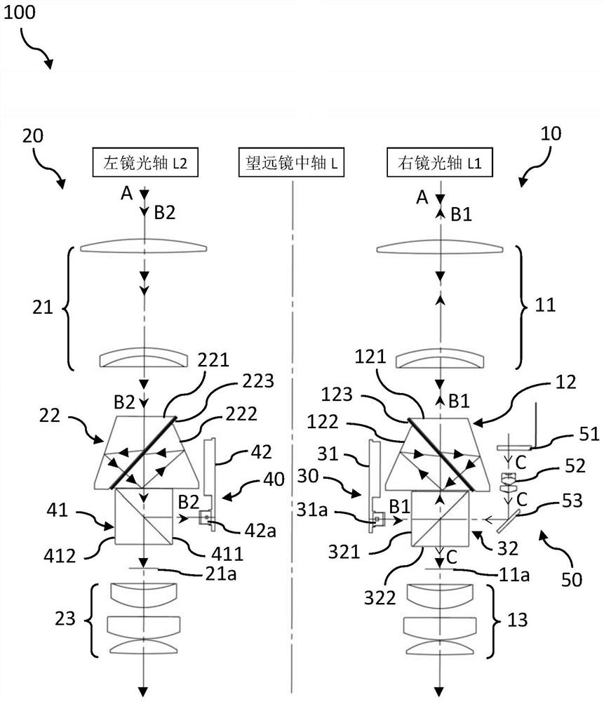
[0039] figure 1 It is the optical principle block diagram of the straight barrel type binocular ranging telescope in the embodiment of the present invention.

[0040] Such as figure 1 As shown, in this embodiment, the straight-tube binocular ranging telescope 100 is improved on the basis of the existing straight-tube binocular telescope 200, and is used for measuring the distance of a selected object to be measured. The straight barrel binocular ranging telescope 100 includes a right lens barrel part 10, a left lens barrel part 20, a laser emitting coupling device 30, a laser receiving coupling device...


PUM


Abstract

The invention provides a laser emitting coupling device, a laser emitting and display coupling device, a laser receiving coupling device, a laser receiving and display coupling device and a straight tube type double-tube distance measuring telescope. A beam splitter prism is arranged, the beam splitter prism is installed between the emergent surface of a roof prism in an image inversion prism anda focal plane of an objective lens group and is arranged in a manner of sharing the same optical axis with the image inversion prism. The beam splitter prism comprises a first right-angle prism facingthe objective lens group and a second right-angle prism facing the ocular lens group. The inclined plane of the first right-angle prism is used as a first inclined plane and is attached to the inclined plane, as a second inclined plane, of the second right-angle prism; the first inclined surface is plated with a light-splitting high-reflection film for natural light transmission and laser total reflection; the laser transmitters or the laser receivers are correspondingly arranged on the side portions of the first rectangular prisms, and the distances between the light-emitting points of the laser transmitters and the intersection points of the receiving points of the laser receivers and the corresponding optical axes and the corresponding first inclined planes are equal to the distances between the intersection points and the corresponding focal planes.

Description

technical field [0001] The invention belongs to the technical field of laser range-finding telescopes, and in particular relates to a laser emitting coupling device, a laser receiving coupling device and straight-tube type binocular range-finding telescopes. Background technique [0002] The popular civilian binoculars on the market are called prism binoculars, which can be divided into Paul prism binoculars, Abbe prism binoculars and Behan roof prism binoculars according to the characteristics of the rubber prisms used. [0003] Such as Figure 5 As shown, the Behan roof prism binoculars 200 are also called straight-tube binoculars, and the left and right lens tubes (not shown in the figure) are respectively accommodated in order by an objective lens group 210, a relay prism 220 and an eyepiece. Group 230. Since the incident optical axis and the outgoing optical axis of the relay prism 220 are coaxial, and the objective lens group 210 is coaxial with the corresponding eyep...

Claims


Application Information

Patent Timeline
Patent Type & Authority Applications(China)
IPC IPC(8): G02B23/02G02B23/04G02B23/10G02B5/08G02B1/11G01S7/481
CPCG01S7/481G02B1/11G02B5/08G02B23/02G02B23/04G02B23/10
Inventor 陈明书
Owner 上海龙达胜宝利光电有限公司
Why Eureka
Try Eureka