Polishing device with high safety for industrial design

An industrial design and safety technology, applied in grinding/polishing safety devices, grinding drive devices, grinding automatic control devices, etc., can solve the problems of fine dust overflow, manual intervention, high work intensity, etc. The effect of frictional resistance

Inactive Publication Date: 2019-05-03
SHANDONG UNIV OF SCI & TECH
View PDF7 Cites 0 Cited by
  • Summary
  • Abstract
  • Description
  • Claims
  • Application Information

AI Technical Summary

Problems solved by technology

[0004] However, in actual use, there are still many shortcomings, such as manual intervention is required for loading and unloading, the work intensity is high, and some fine dust will still overflow through the filter.

Method used


Image

  • Polishing device with high safety for industrial design
  • Polishing device with high safety for industrial design
  • Polishing device with high safety for industrial design

Examples


Embodiment 1

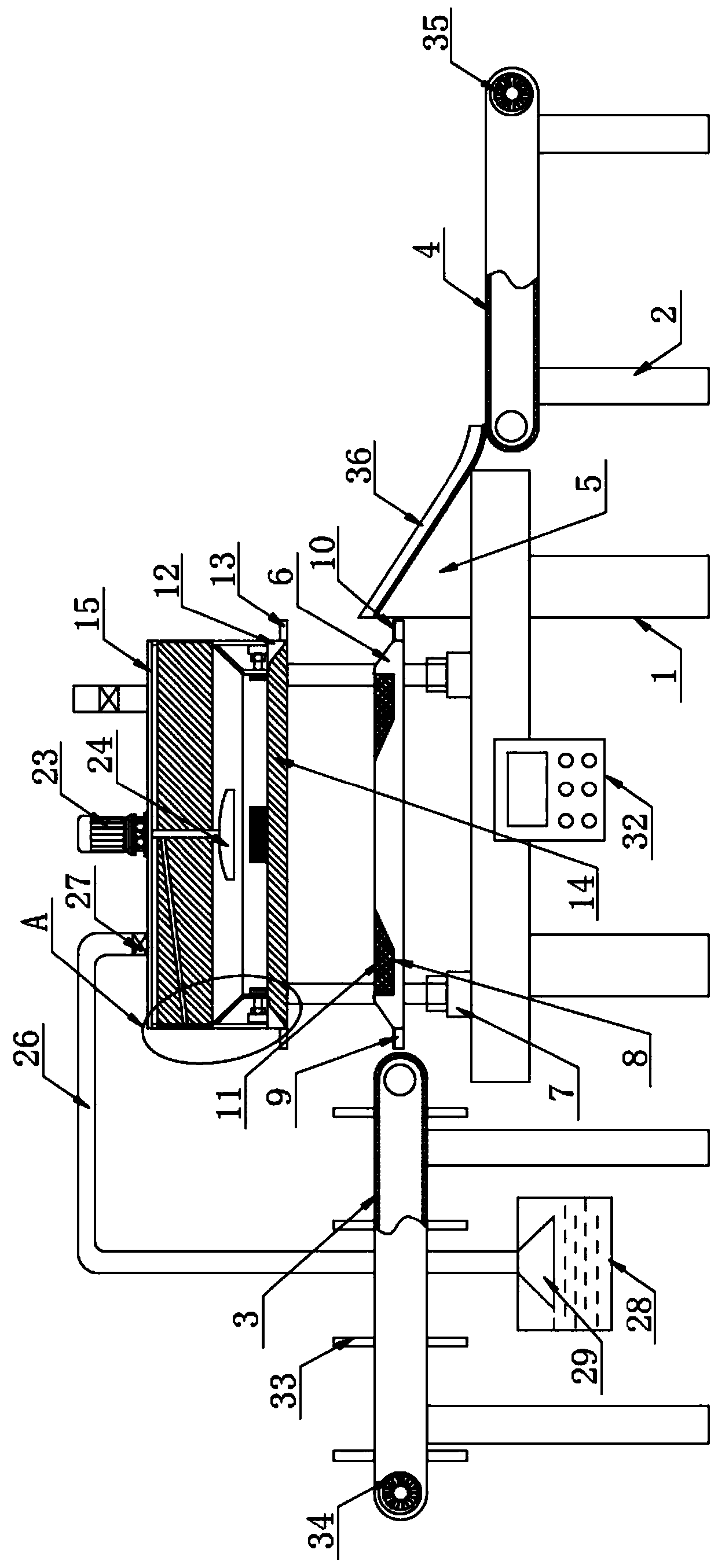
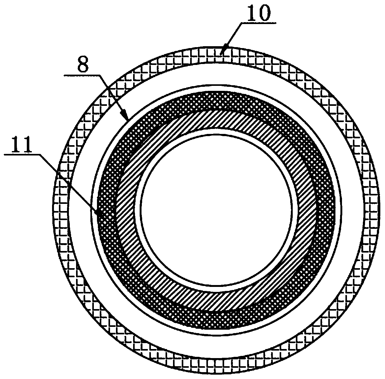
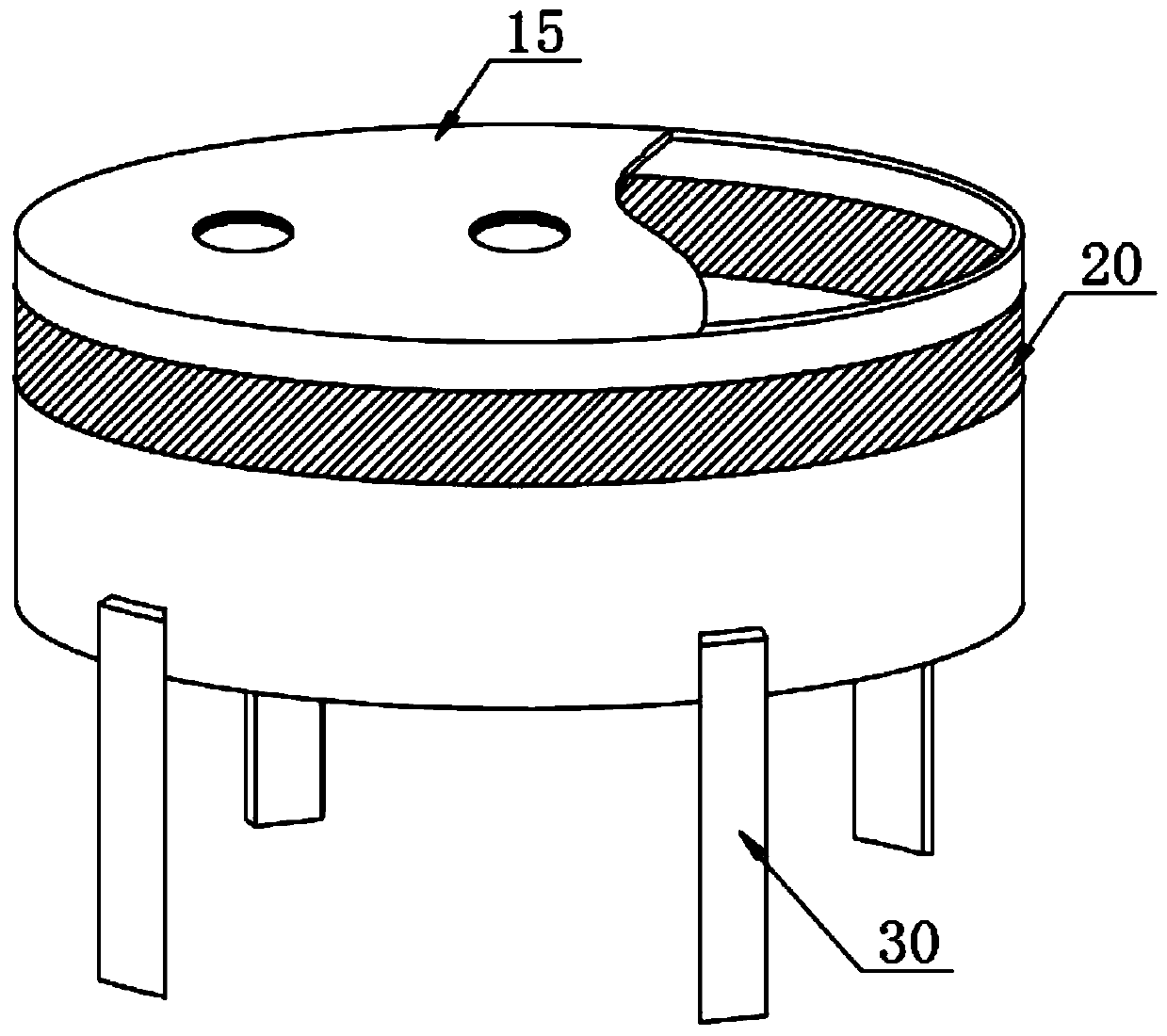
[0028] The present invention provides such Figure 1-8The shown a kind of grinding device with high safety for industrial design includes a frame 1, and brackets 2 are arranged on both sides of the frame 1, and the top of the bracket 2 on one side is provided with a first conveyor belt 3 and The top of the bracket 2 on the other side is provided with a second conveyor belt 4, and one end of the top of the frame 1 is provided with an inclined platform 5, and the bottom end of the inclined platform 5 is smoothly connected with the end of the second conveyor belt 4 at the corresponding position. One side of the inclined platform 5 is provided with a stage 6, and a plurality of first electric push rods 7 are evenly distributed on the bottom edge of the stage 6, and the ends of the first electric push rods 7 are fixedly connected with the stage 6 , the top edge of the stage 6 is provided with a groove 8, the inside of the groove 8 is equipped with a waste box 11, and the bottom end...

Embodiment 2

[0037] The difference from Embodiment 1 is that both sides of the top road of the bracket 2 where the second conveyor belt 4 is located are fixed with limiting guide bars 40, and there are multiple sets of spacing between the two limiting guide bars 40. A baffle 41, the center of both ends of the baffle 41 is provided with a rotating rod, the rotating rod is movably connected to the limit guide bar 40 on the corresponding side through a bearing, and the distance between two adjacent baffles is greater than that of the baffle The width of the plate 41, the inside of the limit guide bar 40 is provided with a first buffer pad 42, the two sides of the baffle plate 41 are provided with a second buffer pad 43, the first buffer pad 42 and the second buffer pad 43 They are all made of silica gel material, which is beneficial to use the inertial force of the sliding workpiece to hit the baffle 41 when the polished workpiece slides along the inclined platform 5 to the top of the second c...


PUM


Abstract

The invention discloses a polishing device with high safety for the industrial design, and particularly relates to the technical field of the industrial design. The polishing device comprises a rack;brackets are arranged on the two sides of the rack correspondingly, a first conveyor belt is arranged at the top of the bracket on one side, and a second conveyor belt is arranged at the top of the bracket on the other side; a sloping bench is arranged at one end of the top of the rack, and the bottom end of the sloping bench is smoothly connected with the end of the second conveyor belt on the corresponding position; and an object table is arranged on one side of the sloping bench, and a plurality of first electric push rods are evenly distributed at the bottom edge of the object table. Workpieces in the polishing process are fed and discharged through the first conveyor belt and the second conveyor belt, and ascending position change of the object table is detected through a film pressure sensor to guarantee orderly automatic proceeding of positioning and polishing work to reduce manual intervention; and meanwhile, dust generated in the polishing process is sucked into a water tank by a fan to prevent the dust from escaping into air and then polluting the environment.

Description

technical field [0001] The invention relates to the technical field of industrial design, more specifically, the invention relates to a grinding device with high safety for industrial design. Background technique [0002] Industrial design, referred to as ID, refers to the design of industrial products based on engineering, aesthetics, and economics. It is also called industrial product design. Industrial design involves psychology, sociology, aesthetics, ergonomics, and mechanical structure. , photography, color science, etc. The industrially designed finished components need to be polished to achieve the effect of modifying the components. [0003] The invention patent of patent application publication number CN 108838771 A discloses a high-safety grinding device for industrial design. Through the use of the cylinder and the geared motor, the cylinder can drive the piston rod to move up and down, and the piston rod can move up and down. Adjust the height of the decelerat...

Claims


Application Information

Patent Timeline
IPC IPC(8): B24B19/00B24B41/00B24B41/06B24B47/12B24B49/16B24B51/00B24B55/00B24B55/04B24B55/06
Inventor 薄其芳贾乐宾
Owner SHANDONG UNIV OF SCI & TECH
Why Eureka
Try Eureka