Up-down sand-ejecting moulding machine and moulding box hydraulic control system thereof

A technology of molding machine and sand injection port, which is applied in the field of casting, and can solve the problems of low sand injection efficiency, wear, and slow sand injection speed, etc.

Pending Publication Date: 2020-09-29
张建诗
View PDF0 Cites 1 Cited by
  • Summary
  • Abstract
  • Description
  • Claims
  • Application Information

AI Technical Summary

Problems solved by technology

The horizontal boxless molding machine in the prior art mainly includes a sand storehouse for storing clay sand and a sand shooting mechanism connected with the sand storehouse. Only by changing the flow direction to the vertical direction through a 90-degree turn angle can it enter the sand shooting mechanism. The clay sand enters the vertical sand shooting mechanism from the sand storehouse on one side. The sand shooting speed will slow down due to the conversion angle, resulting in Reduced sand shooting efficiency
And because the sand-shooting mechanism needs to move downward to compact the sand mold, and the sand storehouse is usually fixed, the sand-shooting mechanism needs to be connected with the sand storehouse in a movable seal, and the sealing structure at the connection between the two will wear out after a period of use And lead to the problem of air leakage and sand leakage
Therefore, how to solve the problem of low sand shooting efficiency in the molding machine in the prior art, and the easy wear of the sealing structure between the sand shooting mechanism and the sand storehouse, resulting in air leakage and sand leakage, is urgently needed by those skilled in the art.

Method used


Image

  • Up-down sand-ejecting moulding machine and moulding box hydraulic control system thereof
  • Up-down sand-ejecting moulding machine and moulding box hydraulic control system thereof
  • Up-down sand-ejecting moulding machine and moulding box hydraulic control system thereof

Examples


Embodiment Construction

[0023] In order to make the purpose, technical solution and advantages of the present invention clearer, the technical solution of the present invention will be described in detail below. Apparently, the described embodiments are only some of the embodiments of the present invention, but not all of them. Based on the embodiments of the present invention, all other implementations obtained by persons of ordinary skill in the art without making creative efforts fall within the protection scope of the present invention.

[0024] Hereinafter, the embodiments will be described in detail in conjunction with the accompanying drawings. In addition, the examples shown below do not limit the content of the invention described in the claims in any way. In addition, all the contents of the configurations shown in the following embodiments are not limited to be essential to the solutions of the invention described in the claims.

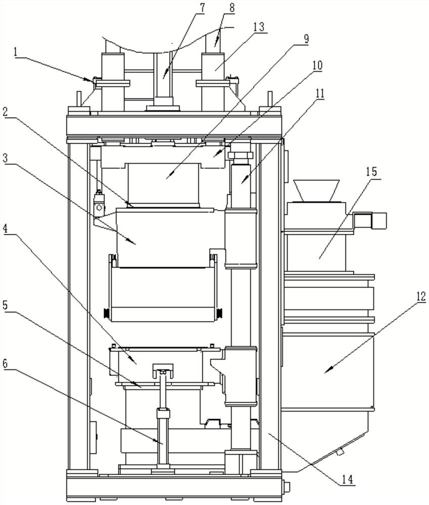
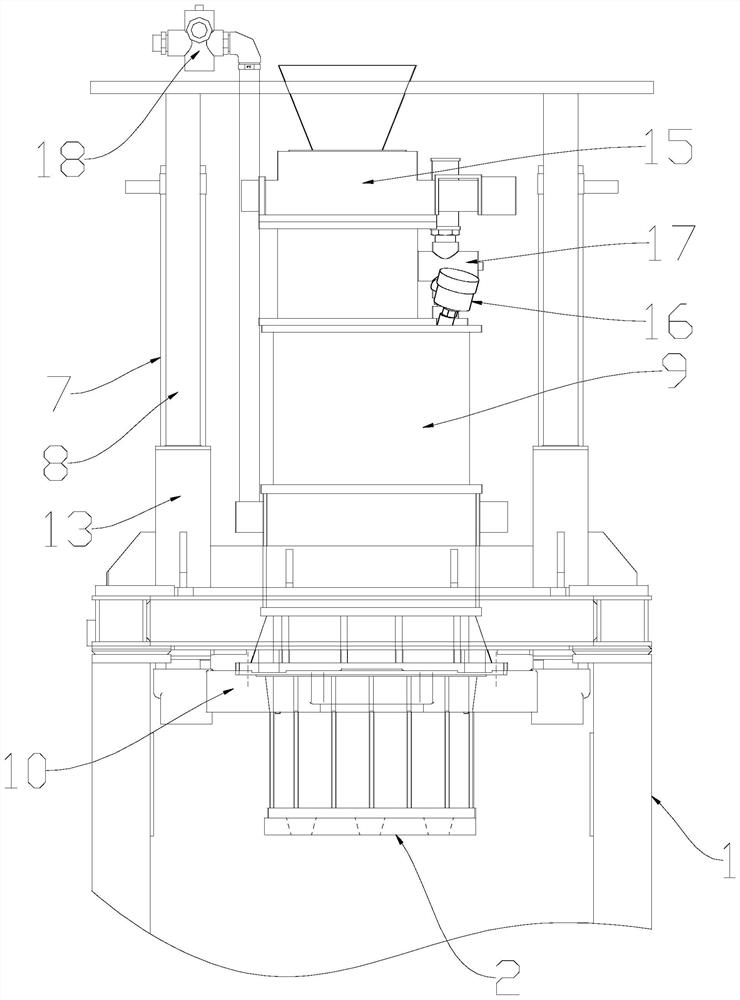
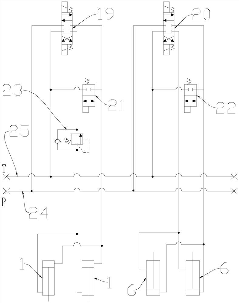
[0025] refer to Figure 1-3 As shown, an upper and lower...


PUM


Abstract

The invention provides an up-down sand-ejecting moulding machine. The up-down sand-ejecting moulding machine comprises a rack, an upper sand bin, a moulding upper box, a lower sand bin, a second compacting plate and a moulding lower box, wherein an upper sand-ejecting hole is formed in the bottom of the upper sand bin; a first compacting plate is arranged at the upper sand-ejecting hole; a throughhole is formed in the first compacting plate; the upper sand bin is connected to the rack through a lifting device; the moulding upper box is connected to a guide rod in a sliding mode; the mouldingupper box is connected to the upper sand bin through an upper box oil cylinder; the lower sand bin is connected to the rack; an upward lower sand-ejecting hole is formed in the lower sand bin; the lower sand-ejecting hole is provided with a second compacting plate, and a through hole is formed in the second compacting plate; the moulding lower box is connected to the guide rod in a sliding mode; and the moulding lower box is connected to the rack through a lower tank oil cylinder. In this way, the up-down sand-ejecting moulding machine is simpler in structure, is lower in fault rate, is free of speed loss during angle conversion, is higher in ejecting-out speed of clay sand, is higher in sand-ejecting rate, can eject sand into a moulding room from upper and lower directions, and enables sand-ejecting efficiency of the up-down sand-ejecting device to be higher.

Description

technical field [0001] The invention relates to the technical field of casting, and more specifically relates to an up and down sand injection molding machine and a hydraulic control system for a molding box thereof. Background technique [0002] In the modern foundry production process, in order to improve the casting efficiency and meet the requirements of modern production, most of the sand molds used in the casting process are made by horizontal boxless molding machines, which are widely used in the foundry machinery industry. The horizontal boxless molding machine in the prior art mainly includes a sand storehouse for storing clay sand and a sand shooting mechanism connected with the sand storehouse. Only by changing the flow direction to the vertical direction through a 90-degree turn angle can it enter the sand shooting mechanism. The clay sand enters the vertical sand shooting mechanism from the sand storehouse on one side. The sand shooting speed will slow down due ...

Claims


Application Information

Patent Timeline
Patent Type & Authority Applications(China)
IPC IPC(8): B22C15/28F15B13/08F15B13/044
CPCB22C15/28F15B13/08F15B2013/0448
Inventor 张建诗
Owner 张建诗
Why Eureka
Try Eureka