
Railway freight car side bearing and railway freight car bogie

A technology for bogies and trucks, applied in the field of rail vehicles, can solve problems such as inability to effectively avoid sand, gravel and dust, increase maintenance and replacement costs, and acid-base environmental pollution, so as to avoid sand, gravel and dust interference, and reduce maintenance and replacement. the cost and the effect of avoiding acid-base pollution

Active Publication Date: 2020-09-25
ZHUZHOU MIYO RUBBER & PLASTIC
View PDF12 Cites 1 Cited by
  • Summary
  • Abstract
  • Description
  • Claims
  • Application Information

AI Technical Summary

Problems solved by technology

[0004] 1. The structure is complicated and the loading and unloading is troublesome, which increases the cost of maintenance and replacement;
[0005] 2. The rubber elastic body in the side bearing is partially exposed, which is easily polluted by the external acid and alkali environment and accelerates aging;
[0006] 3. The open structure of the side bearing cannot effectively avoid sand and dust, which will affect its working performance;
[0007] 4. Larger size and heavier weight

Method used


Image

  • Railway freight car side bearing and railway freight car bogie
  • Railway freight car side bearing and railway freight car bogie
  • Railway freight car side bearing and railway freight car bogie

Examples


Embodiment 1

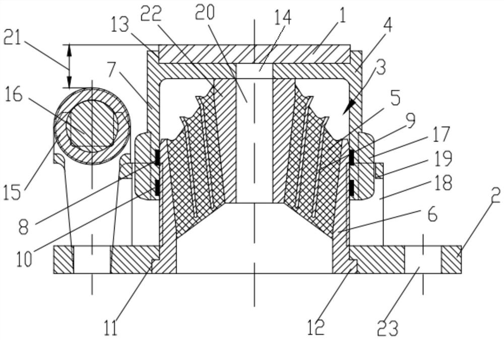
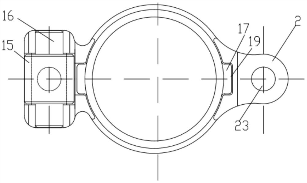
[0035] like Figure 1-2 As shown, the embodiment of the present invention discloses a side bearing of a railway freight car, including a wear plate 1, a side bearing seat 2, a rubber elastic body 3, a roller assembly and a cover plate 4, and the wear plate 1 is installed on the cover plate 4 On the side, the roller assembly is installed on the side bearing 2. Specifically, the roller assembly includes a roller 15 and a roller shaft 16. The roller 15 is sleeved on the roller shaft 16. The roller 15 is connected to the wear plate 1 The distance between the surfaces is the side bearing vertical stroke 21. The rubber elastic body 3 includes an inner core 22, a rubber layer 5 and an outer cover 6 which are sequentially sleeved from the inside to the outside. The outer cover 6 is located under the inner core 22. The inner core 22, rubber The layer 5 and the jacket 6 are vulcanized in one piece. The rubber layer 5 is embedded with multiple metal inner jackets 9, which can effectively...

Embodiment 2

[0043] like Figure 4 As shown, in this embodiment, the main structure is similar to Embodiment 1, and the connection method with the bogie 29 is also the same. The rubber elastic body 3 is closed, the underside of the cover plate 4 is provided with a cover plate sleeve hole 24, the side bearing seat is provided with a side bearing seat sliding sleeve 25, and the upper end of the outer sleeve 6 is sleeved in the cover plate sleeve hole 24 inside, and lean against the top in the socket hole 24 of the cover plate, the lower end is slid in the sliding sleeve 25 of the side bearing seat, and there is a gap between the sliding sleeve 25 of the side bearing seat and the overcoat 6 to prevent the sliding sleeve 25 of the side bearing seat and The guide belt 8 rubbed by the overcoat 6 can solve the wear problem between the side bearing sliding sleeve 25 and the overcoat 6 while sealing the rubber elastic body 3 . In the specific setting of the guide belt 8, there is a gap between the...


PUM


Abstract

The invention discloses a railway freight car side bearing and a railway freight car bogie. The side bearing comprises a wearing plate, a side bearing seat, a rubber elastomer, a roller assembly and acover plate; the wearing plate is mounted on the upper side of the cover plate; the roller assembly is installed on the side bearing seat; the rubber elastomer comprises an inner core, a rubber layerand an outer sleeve which are sequentially connected in a sleeved mode from inside to outside; a plurality of metal inner sleeves are fixedly embedded in the rubber layer; a closed sliding cavity isformed between the side bearing seat and the cover plate; the rubber elastomer is supported on the lower side face of the cover plate; and the rubber elastomer is installed in the sliding cavity. Therubber elastomer of the side bearing is arranged in a closed mode, external acid-base pollution and gravel dust interference are avoided, and the service life of the rubber elastomer which is a vulnerable part is prolonged.

Description

technical field [0001] The invention relates to the technical field of rail vehicles, in particular to a side bearing of a railway freight car and a bogie of a railway freight car. Background technique [0002] Railway freight cars generally consist of car body, bogie, brake device and coupler buffer device. The elastic side bearing is located on the upper part of the bogie, installed between the bolster and the car body, and supports the weight of the car body together with the center plate. There are mainly two types of commonly used railway freight car bogies, one is the gap type rubber body elastic side bearing, which is mainly used in low-speed vehicles (<100kM / h); the other is the constant contact rubber body elastic side bearing, Mainly used in high-speed vehicles (>100kM / h). The longitudinal and lateral rigidity of these two side bearings is generally small (about 5MN / m), and the vertical travel is generally less than 23mm. [0003] Existing side bearing str...

Claims


Application Information

Patent Timeline
Patent Type & Authority Applications(China)
IPC IPC(8): B61F5/14
CPCB61F5/142B61F5/14
Inventor 段扬名彭厦曾立勇黄胜良李桂英张金智
Owner ZHUZHOU MIYO RUBBER & PLASTIC
Learn More