
Rebar hoop bending device

A steel bar bending hoop and hoop bending technology, which is applied in the field of steel bar bending hoop equipment, can solve the problems that the steel bar hoop bending machine cannot be processed at the same time, and the application range is limited.

Pending Publication Date: 2020-09-25
陕西璐江桥隧设备有限公司
View PDF0 Cites 0 Cited by
  • Summary
  • Abstract
  • Description
  • Claims
  • Application Information

AI Technical Summary

Problems solved by technology

[0004] The main purpose of the present invention is to provide a steel bar bending device to at least solve the problem that the steel bar bending machine in the prior art cannot process coiled steel bars and straight steel bars at the same time, resulting in limited application range

Method used


Image

  • Rebar hoop bending device
  • Rebar hoop bending device
  • Rebar hoop bending device

Examples


Embodiment Construction

[0025] It should be noted that, in the case of no conflict, the embodiments in the present application and the features in the embodiments can be combined with each other. The present invention will be described in detail below with reference to the accompanying drawings and examples.

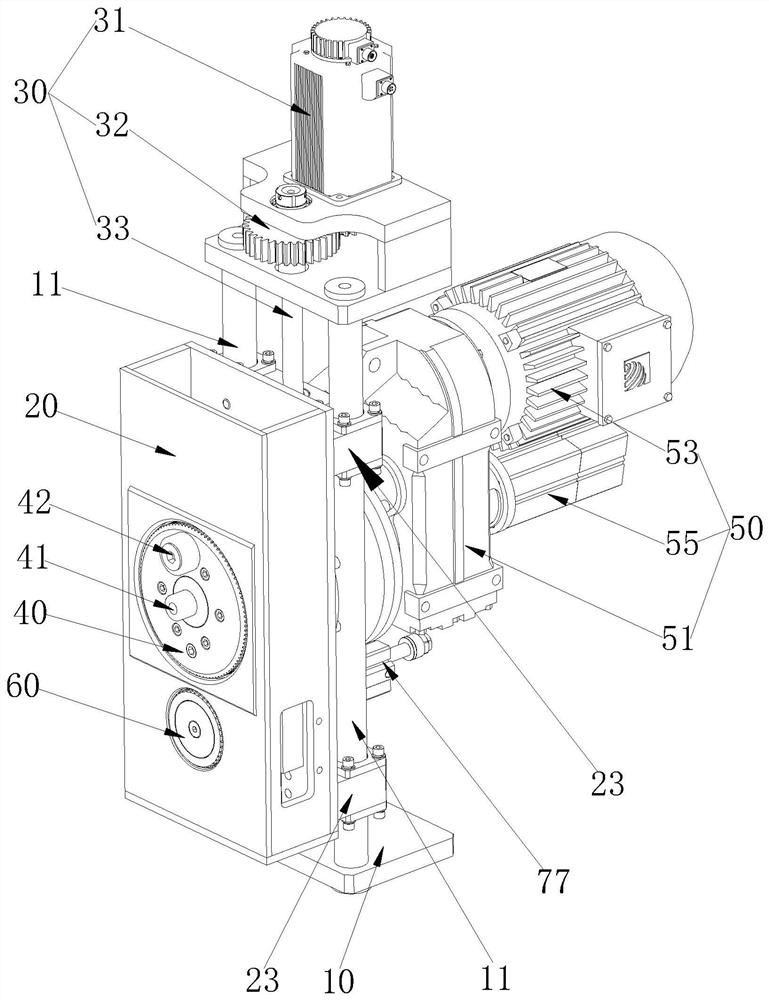
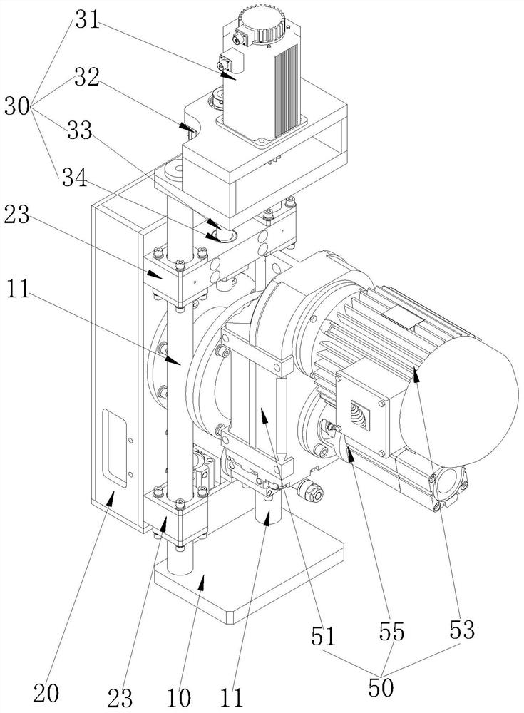
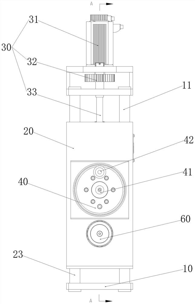
[0026] The steel bar bending hoop device according to the embodiment of the present invention, such as Figure 1 to Figure 4 As shown, the main mounting frame 10, the lifting box body 20, the lifting drive mechanism 30, the driving wheel 40, the driving wheel driving mechanism 50, the driven wheel 60 and the driven wheel driving mechanism 70 are included, and the main mounting frame 10 is fixedly installed on the hoop bending machine. On the base; the lifting box 20 can be installed on the main mounting frame 10 along the height direction of the main mounting frame 10. The inside of the lifting box 20 is provided with a driving wheel accommodation chamber 21 and a driven wheel accommodation cha...


PUM


Abstract

The invention provides a rebar hoop bending device which comprises a main mounting rack, a lifting box body, a lifting driving mechanism, a driving wheel, a driving wheel driving mechanism, a driven wheel and a driven wheel driving mechanism; the lifting box body is mounted on the main mounting rack in an ascending or descending manner in the height direction of the main mounting rack; the drivingwheel around the self axis is rotatably mounted in a driving wheel accommodating cavity and can move in the self axis direction; a core die is arranged at the center of the driving wheel; a thumb wheel is arranged on the circumferential edge of the driving wheel; the driven wheel around the self axis is rotatably mounted in a driven wheel accommodating cavity and can move in the self axis direction and the height direction of the lifting box body; and a hoop bending working face is formed on the front side wall of the lifting box body. The rebar hoop bending device can realize positive bending, reverse bending and automatic material return of a wire rod rebar and a vertical bar rebar and solves the problem in the prior art that a rebar hoop bending machine cannot simultaneously process the wire rod rebar and the vertical bar rebar to cause that the applicable range is limited.

Description

technical field [0001] The invention relates to the field of steel bar bending equipment, in particular to a steel bar bending device. Background technique [0002] In the field of construction and engineering construction, CNC steel bar bending machine has been widely used. In the process of steel bar processing, it is necessary to bend stirrups of different shapes and sizes, and there are specific requirements for the rounded corners of the stirrups. The existing hoop bending machines can only bend hoops for coiled steel bars, but with the development of the market, there are more and more demands for bending hoops for straight steel bars, so there is a corresponding emergence in the market Hoop bending machine for straight bar hoop processing. [0003] However, there is no hoop bending machine that can process both coiled steel bars and straight steel bars on the market. Coiled steel bars and straight steel bars need to be bent separately and independently. The adaptabi...

Claims


Application Information

Patent Timeline
Patent Type & Authority Applications(China)
IPC IPC(8): B21F1/00
CPCB21F1/00
Inventor 袁广学王刚刘鹏飞左斌武王健李利锋陈永方
Owner 陕西璐江桥隧设备有限公司
Learn More