
Passive non-visual-field penumbra imaging method based on transmission window

An imaging method and transmission window technology, applied in the field of optical imaging, can solve problems such as the limited application scope of passive non-field imaging systems, and achieve the effect of solving the application scope limitation and expanding the application scope.

Pending Publication Date: 2020-10-16
HARBIN INST OF TECH
View PDF0 Cites 3 Cited by
  • Summary
  • Abstract
  • Description
  • Claims
  • Application Information

AI Technical Summary

Problems solved by technology

[0007] The purpose of the present invention is to solve the problem of limited application range of the existing passive non-line-of-sight imaging system, and the present invention provides a passive non-line-of-sight penumbra imaging method based on a transmission window

Method used


Image

  • Passive non-visual-field penumbra imaging method based on transmission window
  • Passive non-visual-field penumbra imaging method based on transmission window
  • Passive non-visual-field penumbra imaging method based on transmission window

Examples


Embodiment Construction

[0065] The following will clearly and completely describe the technical solutions in the embodiments of the present invention with reference to the accompanying drawings in the embodiments of the present invention. Obviously, the described embodiments are only some, not all, embodiments of the present invention. Based on the embodiments of the present invention, all other embodiments obtained by persons of ordinary skill in the art without creative efforts fall within the protection scope of the present invention.

[0066] It should be noted that, in the case of no conflict, the embodiments of the present invention and the features in the embodiments can be combined with each other.

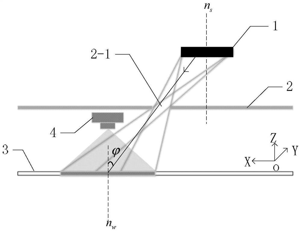
[0067] see figure 2 Describe this embodiment, a transmission window-based passive non-visual penumbra imaging method described in this embodiment, the specific process of the method includes:

[0068] Step 1. The luminous target object 1 is incident on the receiving surface 3 through the transm...


PUM


Abstract

The invention discloses a passive non-visual-field penumbra imaging method based on a transmission window, and relates to the field of optical imaging. The problem that the application range of an existing passive non-vision-field imaging system is limited is solved. The method comprises the steps that 1, a light-emitting target object enters a receiving surface through a transmission window in ashielding object, a penumbra is formed on the receiving surface, an image of the penumbra formed on the receiving surface is collected through a camera, and the collected image is sent to an upper computer; 2, the upper computer obtains a penumbra intensity vector y according to the received image; 3, a forward transmission matrix A of the target object is obtained according to the physical positions of the target object and the penumbra in the scene; 4, an intensity vector f of the target object is obtained according to the obtained penumbra intensity vector y and the forward transmission matrix A; and 5, a target object image f'is obtained according to the intensity vector f of the target object. The method is mainly used for image reconstruction of the target object.

Description

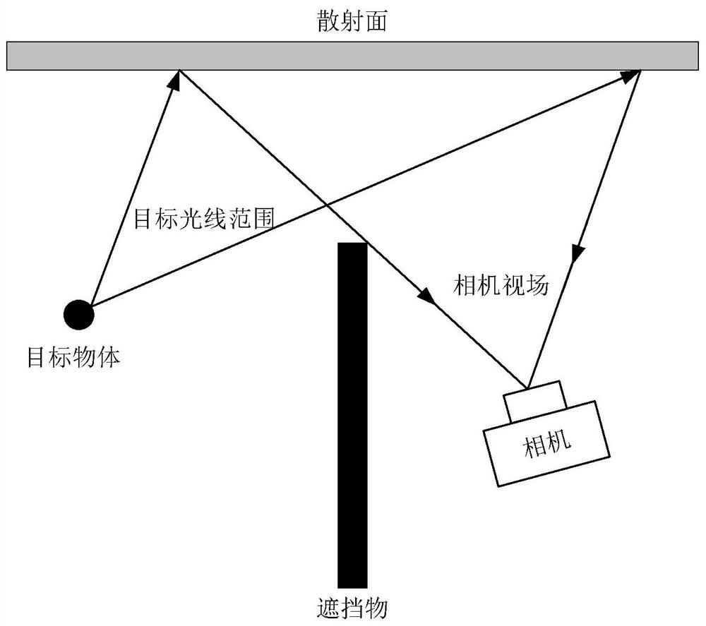
technical field [0001] The invention relates to the field of optical imaging. Background technique [0002] In various complex scenes such as urban buildings, urban underground pipelines, wild vegetation coverage areas, and disaster areas after earthquakes, objects such as walls, street corners, obstacles, and vegetation often form rigid blocks for light. Under such circumstances, the field of view of traditional imaging systems is almost completely lost, and imaging of the target is almost impossible. [0003] In recent years, driven by the rapid development of computational optical imaging, an emerging research field, non-line-of-sight imaging technology has been developed specifically for the above situations. The non-line-of-sight imaging technology can reconstruct the image of the target by capturing the scattered light or reflected light formed by the target light in the surrounding scene. For details, see figure 1 . [0004] Non-line-of-sight imaging means that whe...

Claims


Application Information

Patent Timeline
Patent Type & Authority Applications(China)
IPC IPC(8): G06T15/06G06T15/20
CPCG06T15/06G06T15/20
Inventor 靳辰飞苏晴杨杰乔凯唐勐沈志强张思琦刘丽萍贾乐庚习宇阳
Owner HARBIN INST OF TECH
Learn More