Waste battery smashing device
A technology of waste batteries and crushing devices, which can be used in battery recycling, waste collector recycling, filtering and screening, etc., and can solve problems such as inability to recycle well
- Summary
- Abstract
- Description
- Claims
- Application Information
AI Technical Summary
Problems solved by technology
Method used
Image
Examples
Embodiment 1
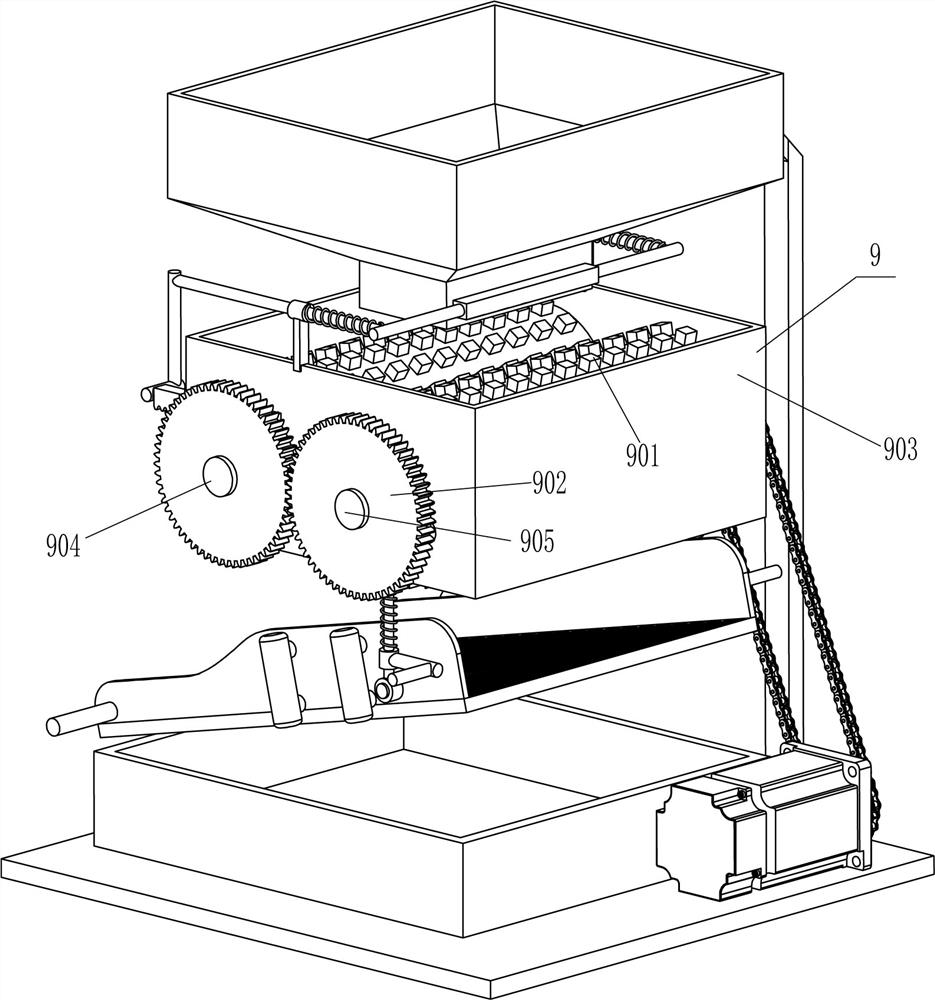
[0022] Reference Figure 1-Figure 4 , A waste battery crushing device, including a bottom plate 1, a collection frame 2, a frame 3, a crushing assembly 9 and a screening assembly 10. The top and the front and back sides of the bottom plate 1 are fixedly connected to the frame 3, and the upper part of the frame 3 on the front and back sides There is a crushing assembly 9 between the top and the left side of the bottom plate 1, and a screening assembly 10 is set between the lower parts of the front and rear sides of the frame 3. The screening assembly 10 is connected and matched with the crushing assembly 9, and the top right middle part of the bottom plate 1 is fixed A collection box that can collect used battery blocks 2.
[0023] The crushing assembly 9 includes a crushing roller 901, a rotating gear 902, a stop frame 903, a first rotating shaft 904, a second rotating shaft 905, a servo motor 906, a first sprocket 907, a second sprocket 908, and a chain 909. A block frame 903 i...
Embodiment 2
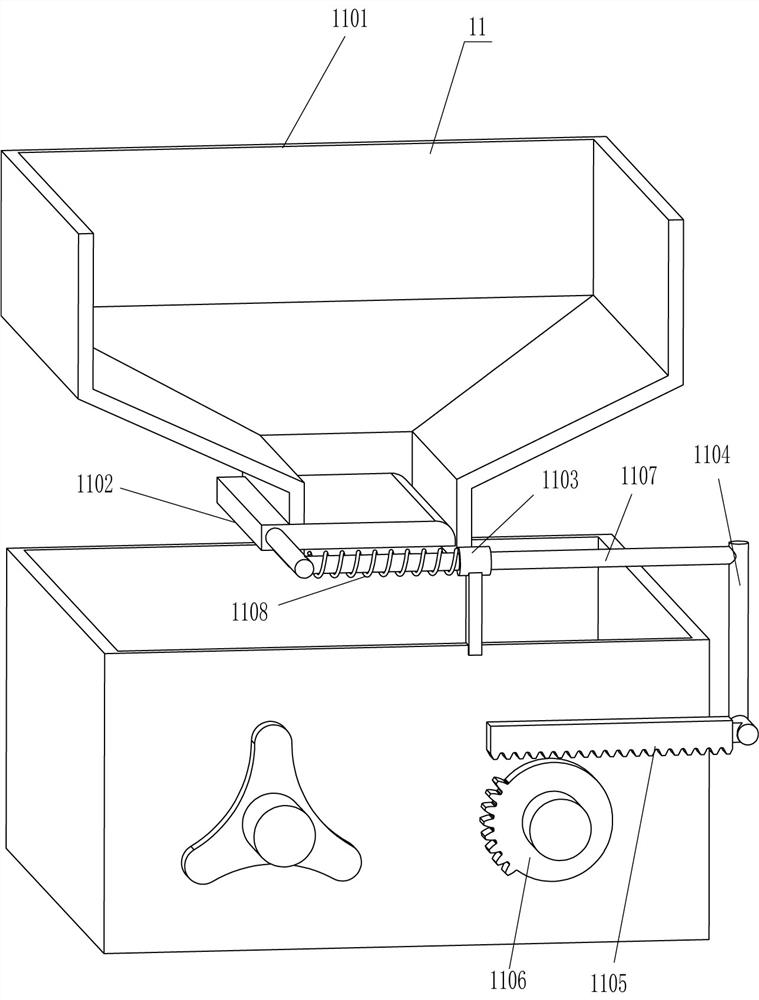
[0029] Reference figure 1 with Figure 5 Compared with the first embodiment, the main difference of this embodiment is that in this embodiment, it also includes a blanking assembly 11, which includes a blanking hopper 1101, a baffle 1102, a supporting sleeve 1103, a connecting frame 1104, and a rack 1105. Toothless gear 1106, L-shaped rod 1107 and second spring 1108. A lower hopper 1101 is installed between the tops of the front and rear frames 3. The lower left side of the lower hopper 1101 is slidingly provided with a baffle 1102 and a baffle 1102 Cooperating with the lower hopper 1101, the front and rear parts of the top right side of the baffle frame 903 are fixedly connected with a support sleeve 1103. The support sleeve 1103 is provided with a sliding L-shaped rod 1107. The inner ends of the L-shaped rods 1107 on the front and rear sides are respectively connected with the baffle The left parts of the front and rear sides of 1102 are fixedly connected. A second spring 1108...
Embodiment 3
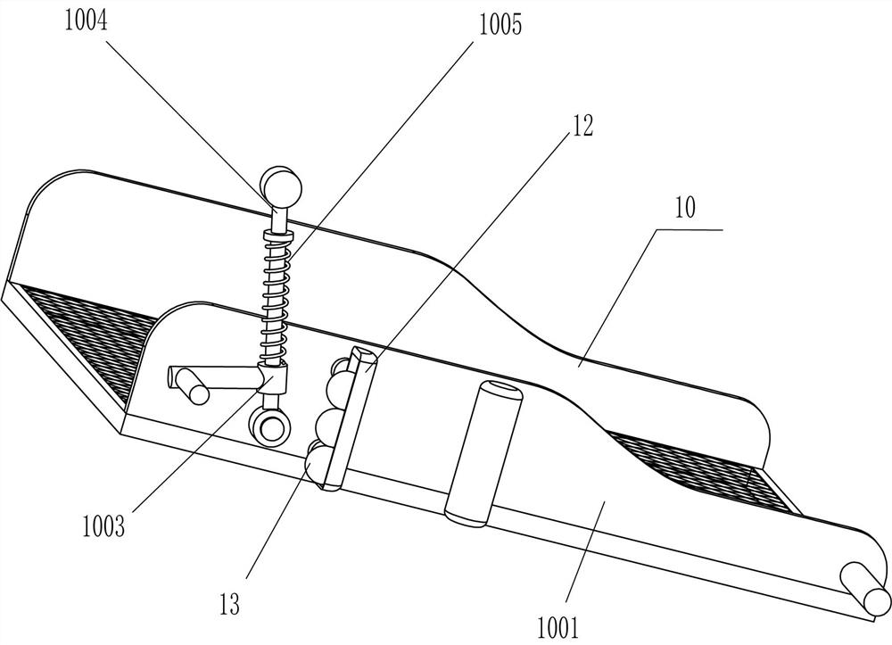
[0032] Reference Figure 4 Compared with embodiment 1 and embodiment 2, the main difference of this embodiment is that in this embodiment, it also includes a hollow sleeve 12 and a steel ball 13, and the left part of the front and rear sides of the frame 1001 are fixed with two hollow In the sleeve 12, three steel balls 13 are slidably arranged in the hollow sleeve 12.
[0033] When the screen frame 1001 swings up and down, the screen frame 1001 also drives the hollow sleeve 12 to swing up and down. The hollow sleeve 12 swings up and down to drive the steel ball 13 to swing up and down. The steel ball 13 swings up and down through the hollow sleeve 12 to vibrate the screen frame 1001. The vibration of the screen frame 1001 causes the stuck used battery blocks to fall. When the net frame 1001 stops swinging, the hollow cylinder also stops driving the steel ball 13 to swing up and down. In this way, it can be avoided that the used battery block is stuck on the screen frame 1001 an...
PUM
 Abstract
Description
Claims
Application Information
 - R&D Engineer
- R&D Manager
- IP Professional
- Industry Leading Data Capabilities
- Powerful AI technology
- Patent DNA Extraction
Browse by: Latest US Patents, China's latest patents, Technical Efficacy Thesaurus, Application Domain, Technology Topic, Popular Technical Reports.
© 2024 PatSnap. All rights reserved.Legal|Privacy policy|Modern Slavery Act Transparency Statement|Sitemap|About US| Contact US: help@patsnap.com


