DC transformer topology and control method based on three-level clllc resonant converter

A resonant converter and DC transformer technology, which is applied in the direction of converting DC power input to DC power output, regulating electrical variables, and controlling/regulating systems, etc., can solve the problems of large number of DC transformer modules, high probability of system failure and high cost. , to achieve the effect of reducing the number of system modules, reducing the number of switching devices, and reducing ripple

Active Publication Date: 2021-08-27
XIAN XJ POWER ELECTRONICS TECH +2
View PDF9 Cites 0 Cited by
  • Summary
  • Abstract
  • Description
  • Claims
  • Application Information

AI Technical Summary

Problems solved by technology

[0008] Aiming at the problems of existing DC transformer modules, such as large number, large volume, high cost, and high probability of system failure, a DC transformer topology and control method based on a three-level CLLLC resonant converter is proposed. This topology has the characteristics of high voltage level , thereby reducing the number of modules required for the DC transformer system, reducing the system footprint and cost, and reducing the probability of system failure

Method used


Image

  • DC transformer topology and control method based on three-level clllc resonant converter
  • DC transformer topology and control method based on three-level clllc resonant converter
  • DC transformer topology and control method based on three-level clllc resonant converter

Examples


Embodiment Construction

[0038] In order to make the object, technical solution and advantages of the present invention clearer, the present invention will be further described in detail below in combination with specific embodiments and with reference to the accompanying drawings. It should be understood that these descriptions are exemplary only, and are not intended to limit the scope of the present invention. Also, in the following description, descriptions of well-known structures and techniques are omitted to avoid unnecessarily obscuring the concept of the present invention.

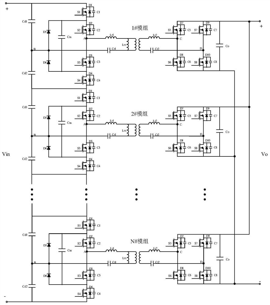
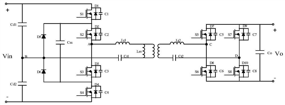
[0039] figure 1 The topology structure diagram of the three-level bidirectional CLLLC DC transformer system for DC distribution network proposed by the present invention, in which N sub-modules are connected in series on the high-voltage side, and N sub-modules are connected in parallel on the low-voltage side. This topology is applied to medium-voltage DC busbars and low-voltage Voltage conversion between DC buses and b...


PUM


Abstract

The present invention relates to a DC transformer topology and control method based on a three-level bidirectional CLLLC resonant converter. The topology includes a high-voltage side topology, a low-voltage side topology, and a bidirectional CLLLC resonant converter; the high-voltage side topology includes N half-bridges connected in series For a three-level circuit, the low-voltage side topology includes N full-bridge circuits connected in series, and each set of half-bridge three-level circuits and full-bridge circuits are correspondingly connected through the bidirectional CLLLC resonant converter. This topology has the characteristics of high voltage level, thereby reducing the number of modules required for the DC transformer system, reducing the system footprint and cost, and reducing the probability of system failure. Moreover, this topology adopts the equivalent pulse expansion wave method, which can realize bidirectional energy flow, full range soft switching, and voltage sharing for series devices. The invention proposes inter-module phase-shift control, which reduces the ripple of the total output current of the low-voltage side parallel modules. The topological structure of N modules with the high-voltage side connected in series and the low-voltage side connected in parallel is suitable for high-voltage and large-capacity applications.

Description

technical field [0001] The invention relates to the technical field of transformer design, in particular to a DC transformer topology and control method based on a three-level CLLLC resonant converter. Background technique [0002] The two-level LLC resonant converter has been more and more widely used in the industry because of its simple structure and superior soft switching characteristics, but it mainly has the following disadvantages: [0003] 1) The voltage stress of the switch tube in the two-level topology is relatively large, especially in higher voltage applications, multiple modules need to be connected in series to meet the requirements, and more modules connected in series will increase the probability of system failure and increase the size of the system. Large size, increased cost, affects the stability and reliability of the system, and increases the workload of system maintenance and system footprint; [0004] 2) At present, the three-level LLC topology is ...

Claims


Application Information

Patent Timeline
Patent Type & Authority Patents(China)
IPC IPC(8): H02M3/335
CPCH02M3/3353H02M1/0058Y02B70/10
Inventor 柳龙陈雪曹建博黄辉龚培娇辛德锋王林吴金龙
Owner XIAN XJ POWER ELECTRONICS TECH
Why Eureka
Try Eureka