Electric power and home information monitoring system, method, equipment and medium

An information monitoring and power technology, applied in information technology support systems, power network operating system integration, electrical components, etc., to solve problems such as the failure of two-way flow of information, the inability to provide fire prevention, and the no-load identification function of power distribution systems.

Pending Publication Date: 2021-02-02
南寅
View PDF5 Cites 1 Cited by
  • Summary
  • Abstract
  • Description
  • Claims
  • Application Information

AI Technical Summary

Problems solved by technology

[0003] The existing technical solutions have the following problems: 1. The information between all nodes in the entire transmission and distribution process from the power distribution network to the end user cannot realize two-way flow; 2. The traditional power distribution system has no load identification function
It cannot bring more benefits to power companies, power users, related electrical manufacturers and society; 3. The traditional power distribution system has no early warning and identification functions of fault arcs, and cannot provide more fire prevention caused by fault arcs and value-added 4. The traditional power distribution network to the end user power distribution system cannot protect users, and there is no electric fire warning and alarm function; 5. The power distribution system does not have F-type or B-type residual current protection; 6. The power distribution system does not have It has the monitoring function of home security, home environment, home smart appliances, and smart auxiliary equipment

Method used


Image

  • Electric power and home information monitoring system, method, equipment and medium
  • Electric power and home information monitoring system, method, equipment and medium
  • Electric power and home information monitoring system, method, equipment and medium

Examples


no. 1 example

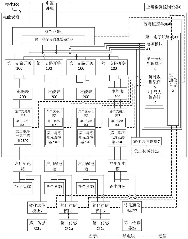
[0079] Such as Figure 1 to Figure 36 As shown, this embodiment discloses a power and home information monitoring system. In this embodiment, the system includes a main circuit breaker 1 , at least one first sensor 2 , at least one electric energy meter 200 , at least one branch switch, a first analysis and processing unit 4 and at least one first communication unit 5 .

[0080] Wherein, the main circuit breaker 1 is connected to the power supply at the incoming line end, and at least one single-phase branch is separated from the outgoing line, wherein each single-phase branch is provided with a branch switch and an electric energy meter 200, and the first sensor 2 is arranged on the branch in the road switch.

[0081] The first sensor 2 is used to detect the single-phase branch voltage and current, and transmit the single-phase branch voltage and current to the first analysis and processing unit 4, and the first analysis and processing unit 4 generates the first A monitorin...

no. 2 example

[0196] Such as Figure 39 and Figure 40 As shown, in this embodiment, the first sensor 2 is an independent unit, and the first sensor 2 can be directly connected to a single-phase branch circuit. Preferably, the first sensor 2 , the electric energy meter 200 , the first analysis and processing unit 4 and the first communication unit 5 can be integrated into an organic whole and arranged in the casing 300 . The first sensor 2 can collect the grid signal characteristics of the power distribution circuit.

[0197] Specifically, the electric energy meter 200 may include a third housing 700 . The first sensor 2 of the electric power and home information monitoring system can be put into the third housing 700 , and the first sensor 2 and the electric energy meter 200 are jointly arranged in an integral housing 700 . The third embodiment has the same beneficial effects as the first embodiment. Compared with the first embodiment, the storage position of the first sensor 2 is not i...

no. 3 example

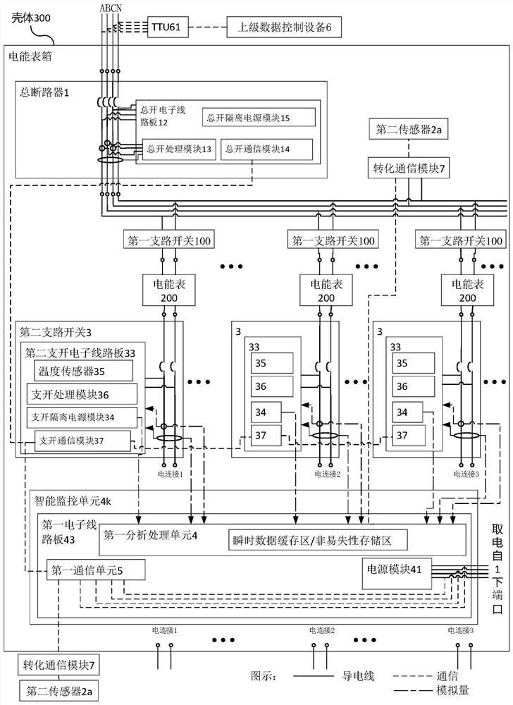
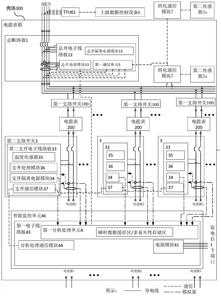
[0200] Such as Figure 41 ~ Figure 50 As shown, the difference from the first embodiment is that in this embodiment, with the continuous deepening of rural power grid transformation, the main circuit breaker 1, the first branch switch 100, the electric energy meter 200, the second branch switch 3 and the intelligent The monitoring unit 4k does not need to be installed in the electric energy meter box, that is, the main circuit breaker 1, the first branch switch 100, the electric energy meter 200, the second branch switch 3 and the intelligent monitoring unit 4k can be installed in the electric energy meter box, or can be installed separately set up. For example, for the first embodiment Figure 1-5 , Figure 24-28 The specific example of the power and household information monitoring system shown, in this embodiment, the main circuit breaker 1, the first branch circuit switch 100, the electric energy meter 200, the second branch circuit switch 3 and the intelligent monitorin...


PUM


Abstract

The invention provides an electric power and home information monitoring system, method, equipment and a medium. The system comprises a main circuit breaker, at least one first sensor, at least one electric energy meter, at least one branch switch, a first analysis processing unit and at least one first communication unit. The wire inlet end of the main circuit breaker is connected with a power supply, the wire outlet end of the main circuit breaker is divided into at least one single-phase branch, each single-phase branch is provided with a branch switch and an electric energy meter, and thefirst sensor is arranged in the branch switch and used for detecting voltage and current of the single-phase branch and transmitting the voltage and current to the first analysis processing unit; andthe first analysis processing unit generates a first monitoring result according to the single-phase branch voltage and current, and the first communication unit transmits the first monitoring resultto superior data control equipment and receives information and / or an instruction of the superior data control equipment. The electric power information of the user in the power use process can be monitored,power use safety is ensured, and information interaction between the power distribution network and terminal users is realized.

Description

technical field [0001] The invention relates to the technical field of power information monitoring, in particular to a power and home information monitoring system, method, device and medium. Background technique [0002] Users will be an integral part of the power system. Encouraging and promoting users to participate in the operation and management of the power system itself is an important feature of the smart grid. In the past, for the power grid, users could only pay electricity bills on time, or check how many kilowatt-hours have passed on their mechanical aluminum disk meters. For power supply companies, mastering the needs of users means better measuring the relationship between supply and demand. Through the statistics of electricity consumption information of users, we can understand the law of electricity consumption in a region from data analysis, and then formulate economical and energy-saving power generation and transmission and distribution schemes in each...

Claims


Application Information

Patent Timeline
IPC IPC(8): H02J13/00
CPCY02B70/30Y04S20/242
Inventor 南寅朱金保王雪楠董郁李勇常杨张太利李灵章龙南添赵志群于雷谷春雷田颖何双武徐富平靳晓恒柴国卿寇籍赵国于纪磊李阳刘万里
Owner 南寅
Why Eureka
Try Eureka