
Electric charge control system

A technology for controlling systems and electricity bills, applied in information technology support systems, electrical components, circuit devices, etc., to solve problems such as large size, unsuitable for centralized management of electrical equipment switches, and unstable pairing addresses.

Pending Publication Date: 2021-04-27
BEIJING PEOPLES ELECTRIC PLANT +4
View PDF1 Cites 0 Cited by
  • Summary
  • Abstract
  • Description
  • Claims
  • Application Information

AI Technical Summary

Problems solved by technology

When the number of users is increasing and the equipment is centrally installed and managed, the wiring is often intricate, which poses a great challenge to the wiring and subsequent maintenance, and will also cause disadvantages such as high cost and large volume. It is not suitable for electrical equipment switches. centralized management of
In addition, the external circuit breaker of the electric energy meter with wireless communication, such as the application number 201910172217.3, discloses a circuit breaker structure applied in the fee control system, which consists of a circuit breaker and a driving module. The driving module includes an execution unit and a control unit. , wireless communication unit, etc. Each circuit breaker control unit has the functions of receiving and processing signals and controls the action of the execution unit. The wireless communication unit has the functions of wireless data transmission and reception, etc., and each circuit breaker is disconnected when the electricity bill is controlled in this way. The circuit breaker alone needs to be paired with the meter for wireless communication. There are problems such as long pairing time, unstable pairing address, etc., and the cost-controlled circuit breaker is large in size and occupies a wide space.

Method used


Image

  • Electric charge control system
  • Electric charge control system
  • Electric charge control system

Examples


Embodiment Construction

[0046]Features and exemplary embodiments of various aspects of the invention will be described in detail below. In the following detailed description, numerous specific details are set forth in order to provide a thorough understanding of the present invention. It will be apparent, however, to one skilled in the art that the present invention may be practiced without some of these specific details. The following description of the embodiments is only to provide a better understanding of the present invention by showing examples of the present invention. The present invention is by no means limited to any specific configurations and algorithms presented below, but covers any modification, substitution and improvement of elements, components and algorithms without departing from the spirit of the invention. In the drawings and the following description, well-known structures and techniques have not been shown in order to avoid unnecessarily obscuring the present invention.

[...


PUM


Abstract

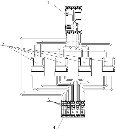
The invention provides an electric charge control system, which comprises a main incoming line switch (1), at least one electric energy meter (2), at least one circuit breaker (3) with an electric operating mechanism and at least one controller (4), and is characterized in that the electric energy meter (2) is provided with a first wireless communication device, and the controller (4) is provided with a second wireless communication device; the electric energy meter (2) sends power-off or power-on information to the controller (4) through the first wireless communication device, and the controller (4) receives the power-off or power-on information through the second wireless communication device and can control the electric operating mechanism to drive the circuit breaker (3) to be switched off or switched on.

Description

technical field [0001] The present application relates to the technical field of electric power information monitoring, in particular to a centralized management electricity charge control system. Background technique [0002] With the intelligentization of my country's power supply network and the continuous improvement of end-user needs, power grid companies have put forward new requirements for energy meters and end-user load switches and smart meter external circuit breakers. One of the requirements is that the smart meter external circuit breaker should be It has the function of remote control, and requires the data interaction between the energy meter and the circuit breaker, as well as the function of reporting the status of the circuit breaker. [0003] The existing traditional electricity charge control system usually connects the electric meter and the charge control circuit breaker through one-to-one wired connection, and each charge control circuit breaker has an ...

Claims


Application Information

Patent Timeline
Patent Type & Authority Applications(China)
IPC IPC(8): H02J13/00H02B1/056
CPCH02B1/056Y02B90/20Y02T90/167Y04S30/12Y04S40/126
Inventor 南寅邓艺军李军挺朱金保李阳李勇董郁常杨张太利章龙周宏亮李灵
Owner BEIJING PEOPLES ELECTRIC PLANT
Learn More