
Laser radar

A technology of laser radar and laser, which is applied in the field of detection radar, can solve the problem of low signal-to-noise ratio of the output signal, and achieve the effect of improving the signal-to-noise ratio, improving the measurement accuracy, and improving the applicability

Pending Publication Date: 2019-03-12
NANJING MOVELASER TECH CO LTD
View PDF0 Cites 14 Cited by
  • Summary
  • Abstract
  • Description
  • Claims
  • Application Information

AI Technical Summary

Problems solved by technology

[0004] In view of this, the purpose of the embodiments of the present invention is to provide a laser radar to solve the problem of low signal-to-noise ratio of the coherent laser radar output signal in the prior art

Method used


Image

  • Laser radar
  • Laser radar
  • Laser radar

Examples


no. 1 example

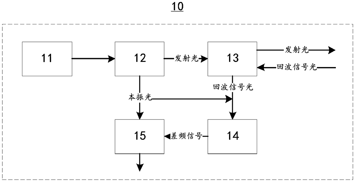
[0032] The applicant found that the working principle of the existing coherent Doppler wind-measuring lidar: a continuous laser with a frequency f is emitted by a coherent light source. The final output frequency is f+f IF The high-power laser signal; the high-power laser signal is sent to the target space through the optical transceiver system, and the aerosol particles in the atmosphere will scatter the laser beam, and the aerosol particles are constantly moving. Due to the Doppler effect, the scattered light will Frequency drift occurs, and the frequency shift Δf is related to the radial motion speed of aerosol particles; the scattered echo signal is collected by the optical transceiver system, and the collected echo signal is mixed with the local oscillator, and the mixed signal is passed through the photoelectric After the detector, a difference frequency signal with Doppler frequency shift of the output two beams of light is obtained; the difference frequency signal is i...

no. 2 example

[0055] Please refer to Image 6 , Image 6 It is a schematic structural diagram of a laser radar 20 provided in the second embodiment of the present invention.

[0056]The lidar 20 includes a laser 11, an optical splitter 12, a telescope system 13, a signal conversion and splitting module 14, a polarization control module 15, an optical frequency shifter 16, an optical amplifier 17 and an optical circulator 18, wherein the laser 11, the optical Splitter 12, telescope system 13, signal conversion and branching module 14, polarization control module 15 are set and connected in the same way as the first embodiment, and optical frequency shifter 16, optical amplifier 17 and optical circulator 18 are connected in sequence in optical Between splitter 12 and telescope system 13. The emission light output by the optical splitter 12 is frequency-shifted and amplified by the optical frequency shifter 16 and the optical amplifier 17, and then sent to the telescope system 13 through the...


PUM


Abstract

The invention provides a laser radar, and relates to the technical field of detection radars. The laser radar comprises a laser device, an optical divider, a telescope system, a signal conversion andshunt module, and a polarization control module; the optical divider divides lasers generated by the laser device into a beam of local oscillator light and a beam of emitted light; the telescope system emits the emitted light to a detection target and receives echo signal light sent back from the detection target; the signal conversion and shunt module acquires difference frequency signals based on the local oscillator light and the echo signal light; the polarization control module rotates the local oscillator light to be in a polarization state same with that of the echo signal light based on the difference frequency signals. The laser radar adjusts the polarization state of the local oscillator light to be same with that of the echo signal light, and thus the signal to noise ratio of output signals of the radar is increased.

Description

technical field [0001] The present invention relates to the technical field of detection radar, in particular to a laser radar. Background technique [0002] Coherent Doppler wind lidar has the advantages of high signal-to-noise ratio, high detection sensitivity, and insensitivity to background sunlight. It can obtain high spatial resolution, high temporal resolution, and high-precision atmospheric wind speed distribution information under clear skies. It is widely used in meteorological research, airport windshear detection, atmospheric turbulence detection and tracking, hurricane tracking, aircraft eddy current detection, military environment forecasting, etc. [0003] The existing coherent Doppler wind lidar splits the continuous laser beam into local oscillator light and emitted light that is scattered into the target space and aerosol particles in the atmosphere. The scattered echo signals are collected by the optical transceiver system. The collected echo signal is mi...

Claims


Application Information

Patent Timeline
Patent Type & Authority Applications(China)
IPC IPC(8): G01S17/95G01S7/481
CPCG01S7/481G01S17/95Y02A90/10
Inventor 张恩惠钱勇李智白栋
Owner NANJING MOVELASER TECH CO LTD
Learn More