Drop-out fuse connecting structure and drop-out fuse

A drop-type fuse and connection structure technology, applied in emergency protection devices, circuits, electrical components, etc., can solve the problems of poor diversion effect, large contact area, good diversion effect, etc., and achieve good contact and large contact area. , good diversion effect

Active Publication Date: 2020-09-22
GUANGDONG POWER GRID CO LTD +1
View PDF15 Cites 0 Cited by
  • Summary
  • Abstract
  • Description
  • Claims
  • Application Information

AI Technical Summary

Problems solved by technology

[0007] The purpose of the present invention is to provide a drop-out fuse connection structure and a drop-out fuse to solve the problems of poor current diversion effect and poor contact due to the use of copper shrapnel in the drop-out fuse, and to ensure that the drop-out fuse is used to connect The structure of the drop-out fuse diversion has a large contact area and good diversion effect

Method used


Image

  • Drop-out fuse connecting structure and drop-out fuse
  • Drop-out fuse connecting structure and drop-out fuse

Examples


Embodiment 1

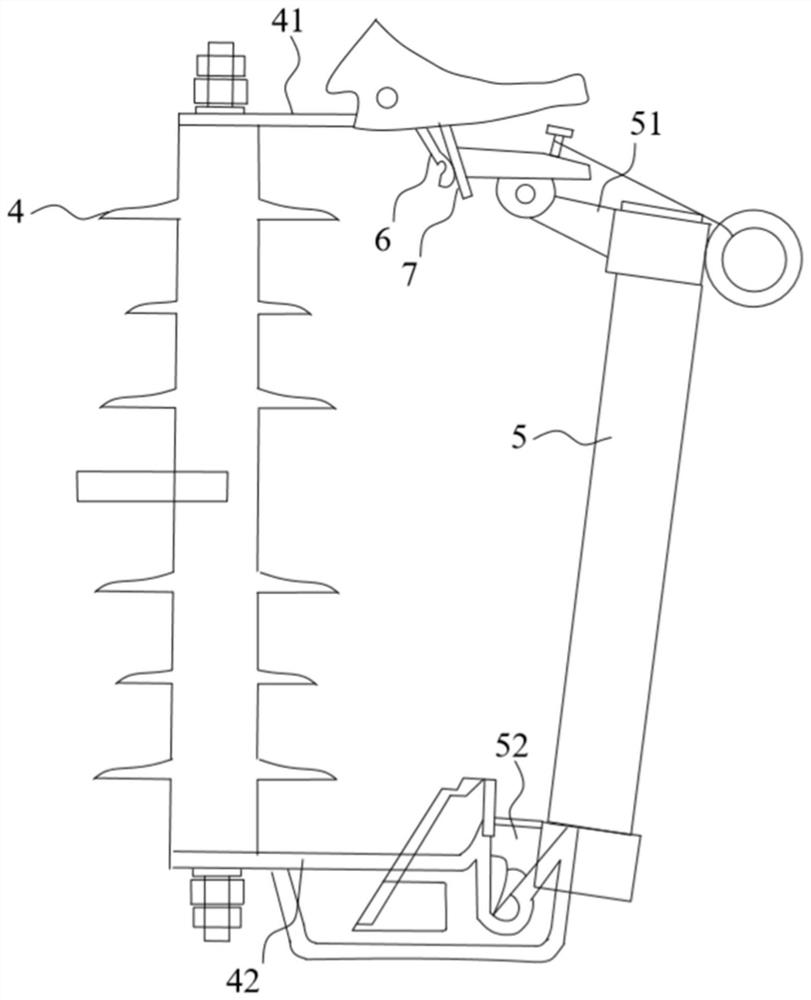
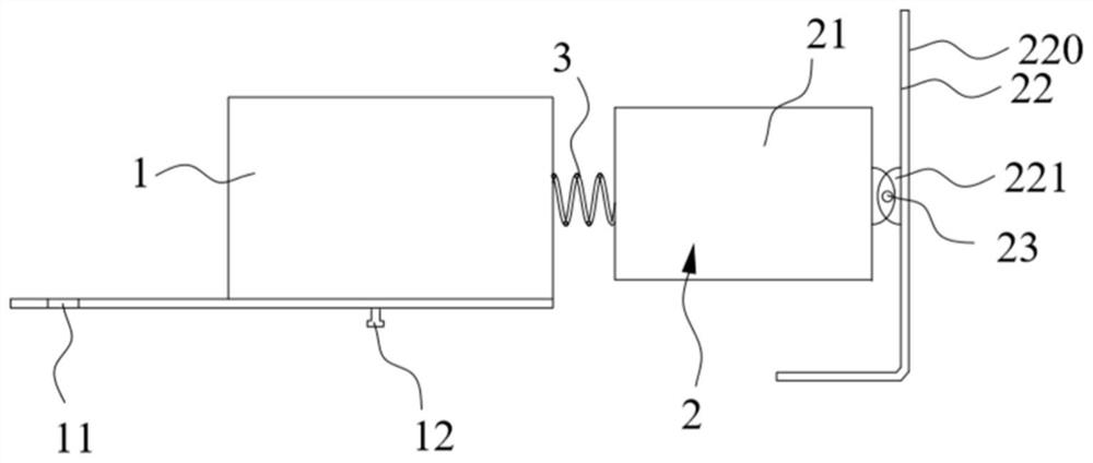
[0035] This embodiment provides a drop-out fuse connection structure, such as figure 2 As shown, the flow diversion between the moving contact and the static contact of the drop-out fuse includes a fixed part 1 and a movable part 2. Among them, one end of the fixed part 1 can be connected with the static contact (including the upper static contact 41 and the lower static contact 42); the movable part 2 has a connecting part 21 and a rotating part 22, and the connecting part 21 is connected to the other end of the fixed part 1. Sliding connection to make the rotating part 22 close to or away from the fixed part 1, the rotating part 22 is rotatably connected to the connecting part 21, the rotating part 22 has a contact plane 220, the contact plane 220 can fit the movable contact (including the upper movable contact 51 and the lower The connecting surface 7 of the moving contact 52). In this embodiment, both the fixed part 1 and the movable part 2 are made of copper to achieve t...

Embodiment 2

[0044] This embodiment is the same as or corresponding parts of the first embodiment using the same reference numerals. For brevity, only the difference from the first embodiment is described. The difference is that: this embodiment provides a drop-out fuse, including implementation Example 1: The drop-out fuse connection structure provided. The drop-out fuse uses the drop-out fuse connection structure provided in the first embodiment to replace the existing copper shrapnel 6, so that the contact area of ​​the diversion is increased, the diversion effect is good, and the original diversion contact area is reduced. The probability of failure is small, which in turn improves the stability of grid operation.


PUM


Abstract

The invention discloses a drop-out fuse connecting structure, which belongs to the technical field of power equipment, is used for guiding flow between a moving contact and a static contact of a drop-out fuse, and comprises a fixed piece and a movable piece, wherein one end of the fixed piece can be connected with the static contact; the movable piece is provided with a connecting part and a rotating part, the connecting part is slidably connected with the other end of the fixed piece to enable the rotating part to be close to or away from the fixed piece, and the rotating part is rotatably connected to the connecting part and provided with a contact plane which can be attached to the connecting surface of the moving contact. The length of the connecting structure is adjustable, the position and the direction of the rotating part can be flexibly adjusted so as to enable the contact plane to be tightly attached to the contact plane of the moving contact of a fuse tube, the contact is good, the flow guide effect is good, the structure is firm, and the connecting structure is not prone to deformation when impacted by external force. The invention further discloses a drop-out fuse which comprises the drop-out fuse connecting structure. The flow guide effect is good, and the fault probability at the flow guide position is reduced.

Description

Technical field [0001] The invention relates to the technical field of power equipment, and in particular to a drop-out fuse connection structure and a drop-out fuse. Background technique [0002] Drop-out fuse is the most commonly used short-circuit protection switch for 10kV distribution line branch lines and distribution transformers. It has the characteristics of economy, easy operation, and strong adaptability to outdoor environments. It is widely used to connect 10kV distribution lines and distribution The electric transformer is used for protection and equipment switching and cutting operations. The drop-out fuse has multiple series such as RW and HRW series. Among them, RW-drop-out fuse is generally used for outdoor use, and it also has multiple models. [0003] For RW3 type, RW11 type and other drop-out fuses, such as figure 1 As shown, it includes a terminal, a composite insulator 4, an upper static contact 41, a lower static contact 42, a fuse tube 5, an upper movable c...

Claims


Application Information

Patent Timeline
IPC IPC(8): H01H85/54H01H85/60
CPCH01H85/54H01H85/60
Inventor 曾思宏郑甦李哲高陈万凯林淮陈凯鹤江嘉欣陈沛松
Owner GUANGDONG POWER GRID CO LTD
Why Eureka
Try Eureka