Efficient lubricating gear coupling

A technology of couplings and gears, applied in the field of high-efficiency lubricating gear couplings, can solve the problems of low lubricating efficiency and easy to throw out lubricating oil, and achieve the effects of high lubricating efficiency, high utilization rate and cost saving.

Inactive Publication Date: 2020-09-22
MAANSHAN IRON & STEEL CO LTD
View PDF6 Cites 2 Cited by
  • Summary
  • Abstract
  • Description
  • Claims
  • Application Information

AI Technical Summary

Problems solved by technology

[0004] The purpose of the present invention is to provide a highly efficient lubricating gear coupling to solve the problem that the existing gear coupling has low lubrication efficiency and the lubricating oil is easily thrown out during operation

Method used


Image

  • Efficient lubricating gear coupling
  • Efficient lubricating gear coupling
  • Efficient lubricating gear coupling

Examples


Embodiment Construction

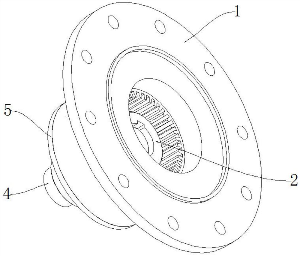
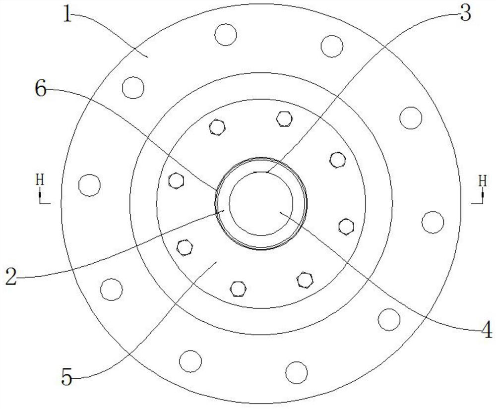
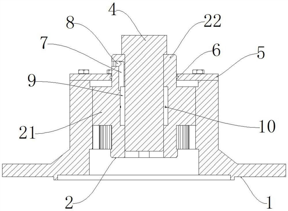
[0024] Figure 8 It shows the cross-sectional structure of the gear coupling in the prior art. It can be seen from the figure that the oil injection part is straight and directly leads to the side of the meshing part. It is difficult for lubricating oil to flow from the oil storage chamber to the other side of the mesh, and the lubrication efficiency is not high; and when the coupling rotates at high speed, once the sealing ring is slightly worn or displaced, the lubricating grease will splash However, it is not only wasteful, but also pollutes the environment and affects peripheral equipment. The temperature of the equipment is generally high during operation, and the oil is flammable, which brings safety hazards. Therefore, the inventor has improved the existing gear coupling.

[0025] The following will clearly and completely describe the technical solutions in the embodiments of the present invention with reference to the accompanying drawings in the embodiments of the pre...


PUM


Abstract

The invention discloses an efficient lubricating gear coupling, and relates to the technical field of couplings. In order to solve the problems that an existing gear coupling is low in lubricating efficiency, and lubricating oil is prone to being thrown out during working, the efficient lubricating gear coupling comprises inner gear rings and outer gear sleeves, the outer gear sleeves are mountedat one ends of shafts and fixedly connected with the shafts through flat keys, meshing areas are arranged in the middles of the outer gear sleeves, the outer gear sleeves are mounted in the inner gearrings and mesh with the inner gear rings, the outer ends of the outer gear sleeves extend out of the inner gear rings, a circle of groove is formed in the inner side of each meshing area, oil cavities are formed between the groove walls and the shafts, L-shaped oil circuits are formed inside the outer ends of the outer gear sleeves, one ends of the L-shaped oil circuits pass through the outer circumferences of the outer ends of the outer gear sleeves and are provided with plugs, the other ends of the L-shaped oil circuits communicate with the grooves, and the meshing areas are provided with aplurality of oiling holes enabling the oil cavities and the junctions between the inner gear rings and the outer gear sleeves to communicate. In the efficient lubricating gear coupling, lubricating grease is high in lubricating efficiency and not prone to being thrown out, and thus resources and the cost are saved.

Description

technical field [0001] The invention relates to the technical field of shaft couplings, in particular to a high-efficiency lubricated gear shaft coupling. Background technique [0002] The gear coupling is composed of two sets of outer tooth sleeves and inner ring gears, which firmly connect the driving shaft and the driven shaft in different mechanisms to rotate together and transmit motion and torque. Compared with other types of Coupling, which has a certain amount of axial displacement and angular displacement, can compensate for offset and ease impact, so it is widely used in various mechanical equipment; in order to avoid tooth surface wear and tear, it is necessary to add lubrication inside the gear coupling grease. [0003] At present, the gear coupling is to process the oil hole on the inner ring gear, and the oil pump is used to inject grease into the cavity between the outer gear sleeve of the coupling and the inner ring gear. The gap is small, so only a small p...

Claims


Application Information

Patent Timeline
Patent Type & Authority Applications(China)
IPC IPC(8): F16D3/18F16N1/00
CPCF16D3/18F16N1/00
Inventor 郑君鲁光耀
Owner MAANSHAN IRON & STEEL CO LTD
Why Eureka
Try Eureka