Dye coating device for spinning

A coating device and dye technology, which is applied in the direction of processing textile material equipment configuration, textile material processing, textile and paper making, etc., can solve the problems of low dyeing efficiency, high consumption cost, long cloth length, etc. Reduce waste and improve functionality

Inactive Publication Date: 2020-09-22
任春宏
View PDF0 Cites 2 Cited by
  • Summary
  • Abstract
  • Description
  • Claims
  • Application Information

AI Technical Summary

Problems solved by technology

[0003] Cloth needs to be dyed during the textile process. Traditional dyeing is mostly placed directly in the dyeing tank for dyeing, and then dried after the dyeing is completed. However, this method will result in low dyeing efficiency, and a large amount of cost will be consumed by artificial dyeing. At the same time, it is also very troublesome when drying. Due to the long length of the cloth, it is very troublesome to change the drying surface frequently when drying.

Method used


Image

  • Dye coating device for spinning
  • Dye coating device for spinning
  • Dye coating device for spinning

Examples


Embodiment 1

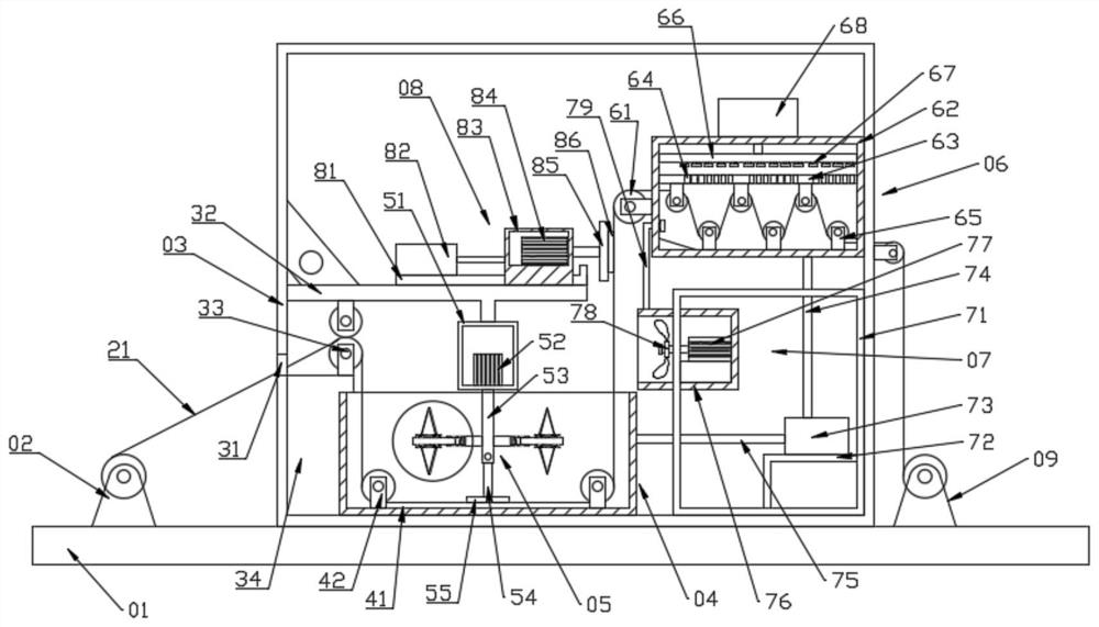
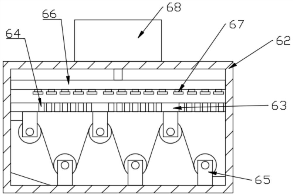
[0026] see Figure 1~4 , in an embodiment of the present invention, a textile dye coating device includes a base 01 on which a feed roll 02, a coating box 03 and a receiving roll 09 are sequentially fixed, and the non-woven fabric wound on the feed roll 02 The cloth 21 is connected with the receiving roll 09 by passing through the coating box 03, wherein the feed roll 02 is used for feeding, and the receiving roll 09 is used for receiving the material, and the coating box 03 is used for dyeing the non-woven fabric 21, Very simple and practical; the coating box 03 is provided with a printing and dyeing assembly 04, a stirring assembly 05 and a drying assembly 06, the stirring assembly 05 is arranged in the printing and dyeing assembly 04 to improve the dyeing effect, and the drying assembly 06 is arranged in The upper right of the printing and dyeing component 04 is used for drying the dyed non-woven fabric 21, which is very simple and practical.

[0027] Further, the coating ...

Embodiment 2

[0036] The coating box 03 is also provided with a smoothing assembly 08 through which the non-woven fabric 21 can be evenly spread. When the non-woven fabric 21 leaves the printing and dyeing assembly 04, a large amount of dye is still attached to the surface. The uniform component 08 can evenly wipe this part of the dye; the smooth component 08 includes a guide rail 81 fixed on the first fixed plate 32, a second fixed box 83 is slidably connected to the guide rail 81, and a second fixed box 83 is fixed in the second fixed box 83. The third motor 84, the output end of the third motor 84 is connected with the smoothing plate 86 on the fixed block 85, can drive the smoothing plate 86 to rotate when the wind hole 64 works, and then smear evenly, the second fixed box 83 and the telescopic cylinder 82 output terminal connection, and then conveniently adjust the position of the second fixed box 83, very simple.

[0037] The working principle of the present invention is: the non-wove...


PUM


Abstract

The invention discloses a dye coating device for spinning, and relates to the technical field of spinning. The dye coating device for spinning comprises a base, wherein a feeding roller, a coating boxand a material collecting roller are sequentially fixedly arranged on the base; non-woven fabric wound on the feeding roller passes through the coating box and is connected to the material collectingroller; a printing and dyeing assembly, a stirring assembly and a drying assembly are arranged in the coating box; the stirring assembly is arranged in the printing and dyeing assembly; the drying assembly is arranged at the right upper side of the printing and dyeing assembly; and an auxiliary assembly and a uniform-coating assembly are further arranged in the coating box. The stirring assemblyarranged in the printing and dyeing assembly can achieve effective stirring effect, so that color is conveniently regulated, and dyeing effect is further favorably improved, and therefore, practicability is high; and an auxiliary assembly can be arranged to improve integral functionality, so that recycling of dyes and drying of non-woven fabric are facilitated.

Description

technical field [0001] The invention relates to the technical field of textiles, in particular to a dye coating device for textiles. Background technique [0002] The original meaning of textile is taken from the general term of spinning and weaving, but with the continuous development and improvement of the textile knowledge system and subject system, especially after the emergence of non-woven textile materials and three-dimensional composite weaving technologies, textile is not only the traditional spinning and weaving Weaving also includes non-woven technology, three-dimensional weaving technology, electrostatic nano-netting technology, etc. Weaving is roughly divided into two processes: spinning and weaving. [0003] Cloth needs to be dyed during the textile process. Traditional dyeing is mostly placed directly in the dyeing vat for dyeing, and then dried after dyeing is completed. However, this method will result in low dyeing efficiency, and a large amount of cost wi...

Claims


Application Information

Patent Timeline
Patent Type & Authority Applications(China)
IPC IPC(8): D06B3/20D06B15/09D06B23/20D06B3/34
CPCD06B3/20D06B3/34D06B15/09D06B23/20D06B23/205
Inventor 任春宏
Owner 任春宏
Why Eureka
Try Eureka