LCLCL high-order DC converter based on stacked bridges and control method
A technology of DC converter and control method, which is applied in the direction of DC power input conversion to DC power output, control/regulation system, high-efficiency power electronic conversion, etc. It can solve the problems of limited voltage input range and voltage input fluctuation, and achieve high Conversion efficiency, stable voltage output, and effect of guaranteed voltage output
- Summary
- Abstract
- Description
- Claims
- Application Information
AI Technical Summary
Problems solved by technology
Method used
Image
Examples
specific Embodiment approach 1
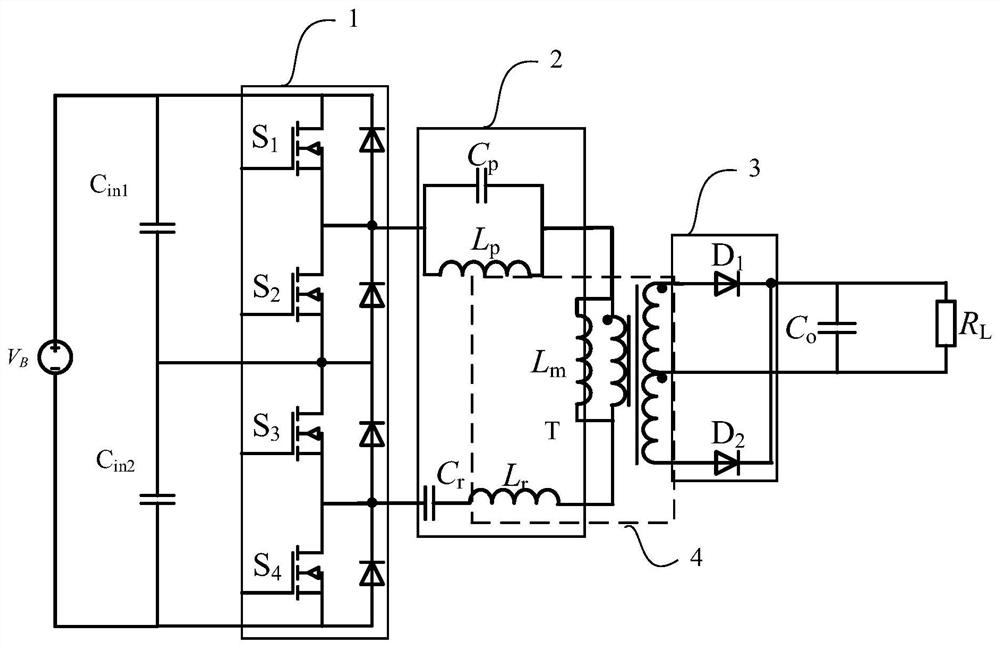
[0048] Specific implementation mode 1. Combination figure 1 As shown, the first aspect of the present invention provides a kind of LCLCL high-order DC converter based on the stacked bridge, including the switching tube S 1 , switch tube S 2 , switch tube S 3 , switch tube S 4 , Resonant capacitance C r , Resonant inductance L r , transformer T, band stop filter inductor L p , Band stop filter capacitor C p , Diode D 1 , Diode D 2 , output capacitance C 0 , Divider capacitor C in1 and the divider capacitor C in2 ;
[0049] Switch tube S 1 , switch tube S 2 , switch tube S 3 and switch tube S 4 connected in turn to form a stack bridge, the switching tube S 1 and switch tube S 2 Constitute the upper bridge arm, the upper bridge arm is connected in parallel with the voltage dividing capacitor C in1 ;Switch tube S 3 and switch tube S 4 It constitutes the lower bridge arm, and the lower bridge arm is connected in parallel with the voltage dividing capacitor C in...
specific Embodiment approach 2
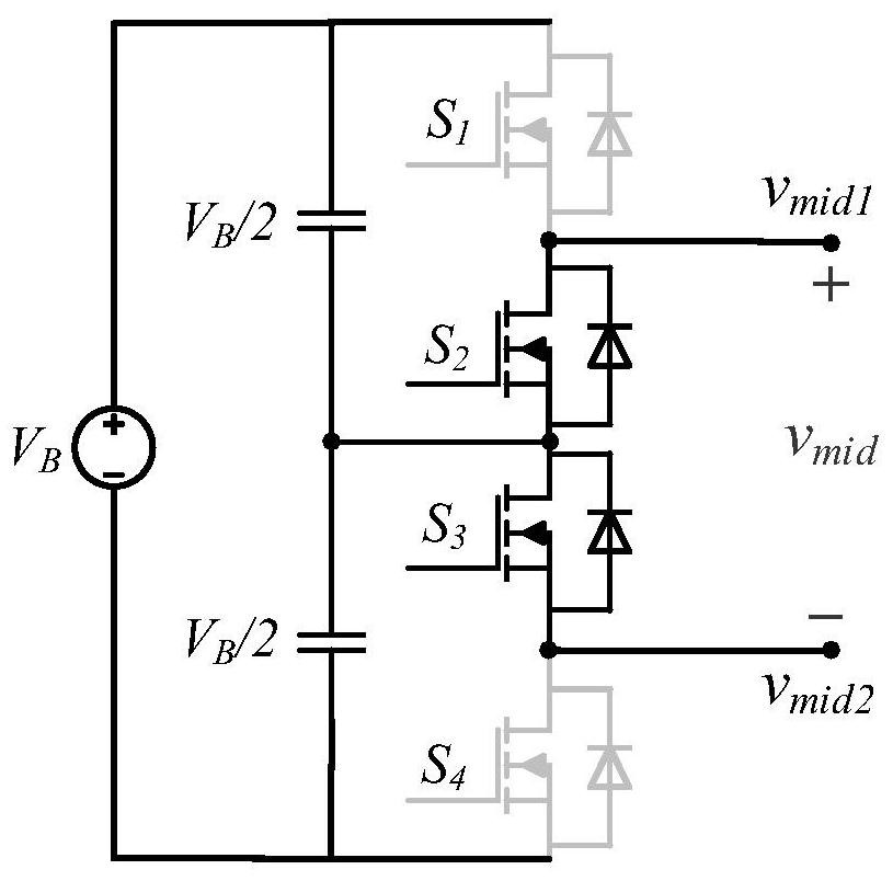
[0058] Specific embodiment two, combine Figure 1 to Figure 19 As shown, another aspect of the present invention also provides a stacked bridge-based LCLCL high-order DC converter control method for realizing the control of the stacked bridge-based LCLCL high-order DC converter, including:
[0059] Sampling the input voltage of the power supply, when the input voltage is in the low-voltage range, at the switching frequency of 1MHz, the switching tube S 1 and switch tube S 4 As the first group of switching tubes, the switching tube S 2 and switch tube S 3 As the second group of switching tubes, control the two groups of switching tubes to alternately work for half the voltage cycle to realize the frequency conversion working mode;
[0060] When the input voltage is in the high-voltage range, and the switching frequency is 500kHz, the switching tubes S are cyclically controlled in sequence 1 and switch tube S 3 , switch tube S 2 and switch tube S 3 , switch tube S 2 and ...
specific Embodiment
[0083] Specific embodiments: the rated input voltage is 170V and 340V, the corresponding rated operating frequency is 1MHz and 500KHz, the output voltage is stable 20V, and the output power is 40W.
[0084] 1. Frequency conversion working mode:
[0085] When the input voltage is 170V, the working mode of frequency conversion is adopted, that is, the traditional LLC resonant power converter mode. At this time, the equivalent input square wave voltage amplitude is the input voltage, and the frequency is 1MHz.
[0086] 2. Double frequency working mode:
[0087] When the input voltage is 340V, the working mode of frequency doubling is adopted. By controlling the switching sequence of the four switching tubes, the amplitude of the input square wave voltage is equal to that of the input voltage. The frequency of the square wave is half of the frequency of the switching tubes, and the frequency is 1MHz.
[0088] 3. When the input voltage is further increased, the operating frequenc...
PUM
 Abstract
Description
Claims
Application Information
 - R&D
- Intellectual Property
- Life Sciences
- Materials
- Tech Scout
- Unparalleled Data Quality
- Higher Quality Content
- 60% Fewer Hallucinations
Browse by: Latest US Patents, China's latest patents, Technical Efficacy Thesaurus, Application Domain, Technology Topic, Popular Technical Reports.
© 2025 PatSnap. All rights reserved.Legal|Privacy policy|Modern Slavery Act Transparency Statement|Sitemap|About US| Contact US: help@patsnap.com


