Automatic mapping method for reinforcement diagram between underground passage auxiliary pump room and tool

An underground passage, automatic drawing technology, applied in special data processing applications, geometric CAD and other directions, can solve the problems of incomplete modification of primitives, calculation errors, low efficiency, etc., to improve drawing efficiency, shorten drawing time, The effect of uniform quality standards

Pending Publication Date: 2020-09-18
WUHAN MUNICIPAL ENG DESIGN & RES INST
View PDF4 Cites 2 Cited by
  • Summary
  • Abstract
  • Description
  • Claims
  • Application Information

AI Technical Summary

Problems solved by technology

[0004] 1. Time-consuming, heavy workload and low efficiency
Even for skilled technicians, it takes a lot of time to draw a set of construction drawings that meet the construction requirements; usually the construction drawings are obtained from the construction drawings of the previous project to increase or decrease the structural size and modify the reinforcement information. Carry out manual calculations, and when there are many reinforcement cross-sections to be designed, all of them are repetitive tasks, which may easily lead to calculation errors or incomplete modification of graphic elements, and the manual workload of design, verification, and review is relatively large, resulting in the overall drawing efficiency low
[0005] 2. The quality of the drawings is poor, and it is difficult to unify the quality standards
This is because the final drawing effect has a lot to do with the designer's design habits, design experience and drawing level. Designers will unconsciously add many subjective factors in the process of drawing. It is difficult to unify styles such as labeling styles, drawing standards and differences in everyone's habits, which will make it difficult to guarantee the drawing quality
[0006] 3. High requirements for designers

Method used


Image

  • Automatic mapping method for reinforcement diagram between underground passage auxiliary pump room and tool
  • Automatic mapping method for reinforcement diagram between underground passage auxiliary pump room and tool
  • Automatic mapping method for reinforcement diagram between underground passage auxiliary pump room and tool

Examples


Embodiment Construction

[0051] Below in conjunction with specific embodiment, further illustrate the present invention, should be understood that these embodiments are only used to illustrate the present invention and are not intended to limit the scope of the present invention, after having read the present invention, those skilled in the art will understand various equivalent forms of the present invention All modifications fall within the scope defined by the appended claims of the present application.

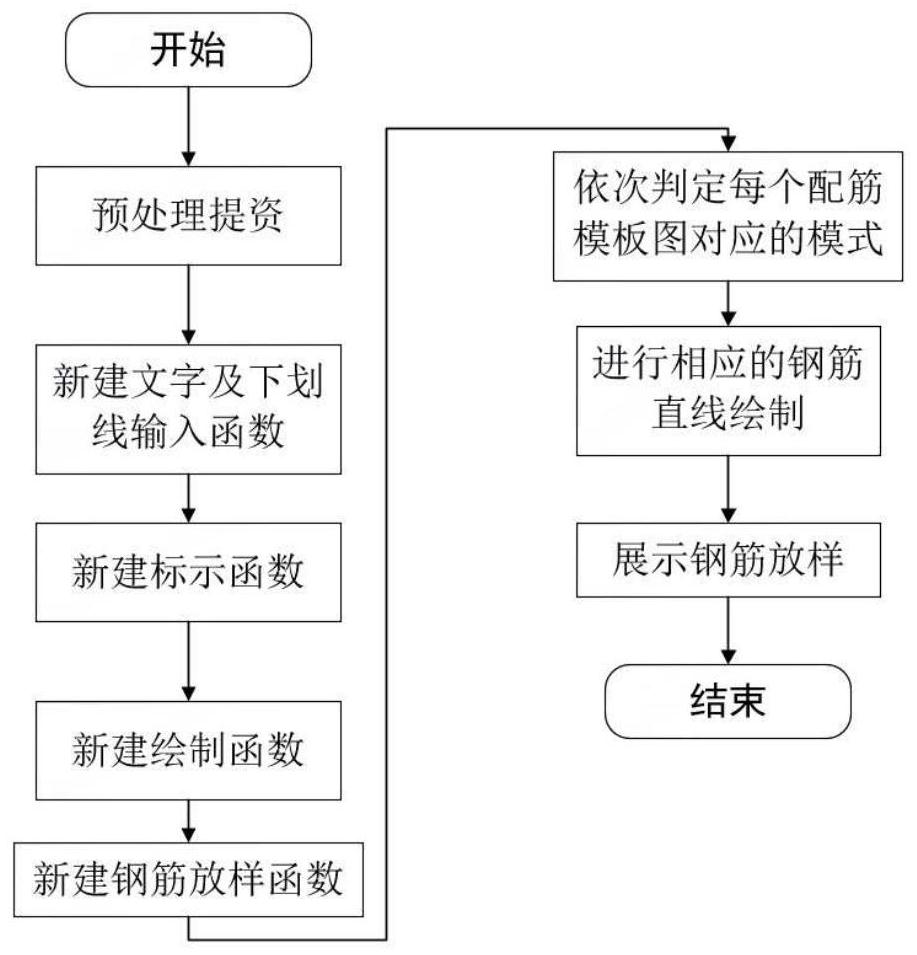
[0052] The embodiment of the automatic drawing method for the reinforcement diagram of the pump room and tool room attached to the underground passage of the present invention is realized by writing in LISP language.

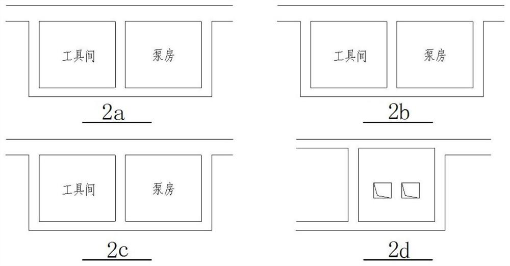
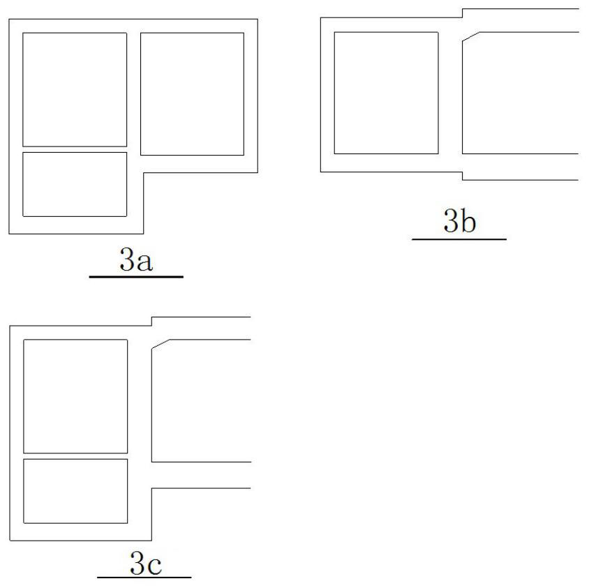
[0053] like figure 1 As shown, the automatic drawing method for the reinforcement diagram of the pump room and tool room attached to the underground passage is suitable for the standardized automatic generation of the reinforcement diagram of the pump room and tool room attached to ...


PUM


Abstract

The invention relates to an automatic mapping method for a reinforcement diagram between an underground passage auxiliary pump room and a tool, which is suitable for standardizing and automatically generating the reinforcement diagram between the underground passage auxiliary pump room and the tool, and comprises the following steps of: preprocessing and providing resources to obtain a reinforcement template diagram set; newly establishing a character and underline input function; newly establishing a marking function; creating a new drawing function; newly building a steel bar lofting function; sequentially judging a mode corresponding to each reinforcement template drawing; drawing corresponding steel bar straight lines according to the mode corresponding to each reinforcement template drawing; and displaying steel bar lofting. The method is extremely short in consumed time and extremely high in efficiency; the drawing quality is high, and the quality standard is unified; and the requirements on designers are greatly reduced.

Description

technical field [0001] The invention relates to the technical field of automatic drawing of reinforcement diagrams, in particular to a method for automatically forming reinforcement diagrams of pump rooms and tool rooms attached to underground passages. Background technique [0002] In the engineering design of underground tunnel and passage construction, construction drawings play the role of comprehensive guidance and planning standards for specific construction technical schemes. Generally speaking, before the construction starts, it is necessary to plan and set up the overall construction plan and determine the construction drawings to ensure the accuracy of the construction process. Therefore, before construction, it is necessary to draw the construction drawings of the drawing object system. In the design process of construction drawings of underground tunnels and passages, considering the functional requirements of the project itself, tunnels and passages are usually...

Claims


Application Information

Patent Timeline
IPC IPC(8): G06F30/13
CPCG06F30/13
Inventor 李清鹏
Owner WUHAN MUNICIPAL ENG DESIGN & RES INST
Why Eureka
Try Eureka