Plugging cover for vent pipe joint of turbine casing of aero-engine
A technology for aero-engine and turbine casings, which is applied in the field of blocking cover of aero-engine turbine casing vent pipe joints, which can solve problems such as easy formation of new redundant objects, insufficient protection of plugs, and inconvenient connections, etc., and achieve a wide range of structural applications , Convenient for standardized production, easy to plug in and take out, and labor-saving effect
- Summary
- Abstract
- Description
- Claims
- Application Information
AI Technical Summary
Problems solved by technology
Method used
Image
Examples
Embodiment 1
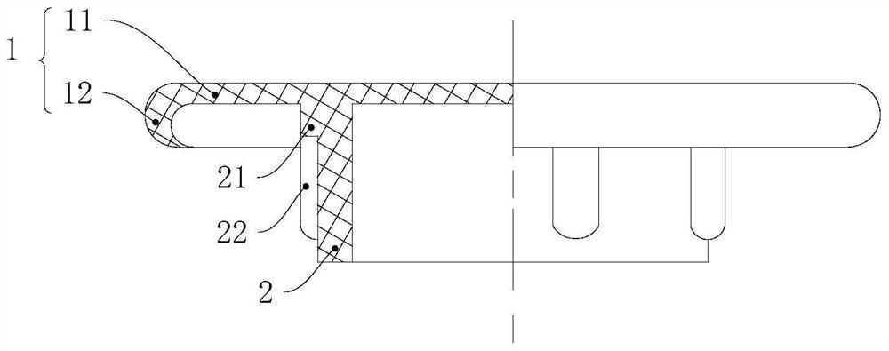
[0040] refer to image 3, a blocking cover for aero-engine turbine casing breather pipe joints, comprising: a cover body 1 and a plug body 2 arranged in the cover body 1, the cover body 1 is a cylindrical structure with one end open and one end closed, and the cover body 1 includes : the bottom surface 11 and the side wall 12 arranged on the periphery of the bottom surface 11; the longitudinal section of the side wall 12 is a hook-shaped arc structure with an opening inward. The plug body 2 is a cylindrical structure with a wall thickness of 8 mm. The end of the plug body 2 close to the cover body 1 is provided with an annular circular platform 21 matching the inner cavity wall of the ventilation pipe. 1 / 3 of the length of body 2,
[0041] refer to Figure 4 , the outer wall of the plug body 2 is provided with 10 positioning ribs 22 uniformly arranged along the circumferential direction of the plug body 2, one end of the positioning ribs 22 is arranged on the round platform ...
Embodiment 2
[0045] refer to Image 6 , The difference between this embodiment and Embodiment 1 is that the longitudinal section of the side wall 12 of the cover body 1 is a planar structure arranged parallel to the outer wall of the vent pipe joint 3, and in this embodiment, the wall of the plug body 2 The thickness is 7mm, the length of the round platform 21 is 1 / 4 of the length of the plug body 2, and the number of positioning ribs 22 is 8.
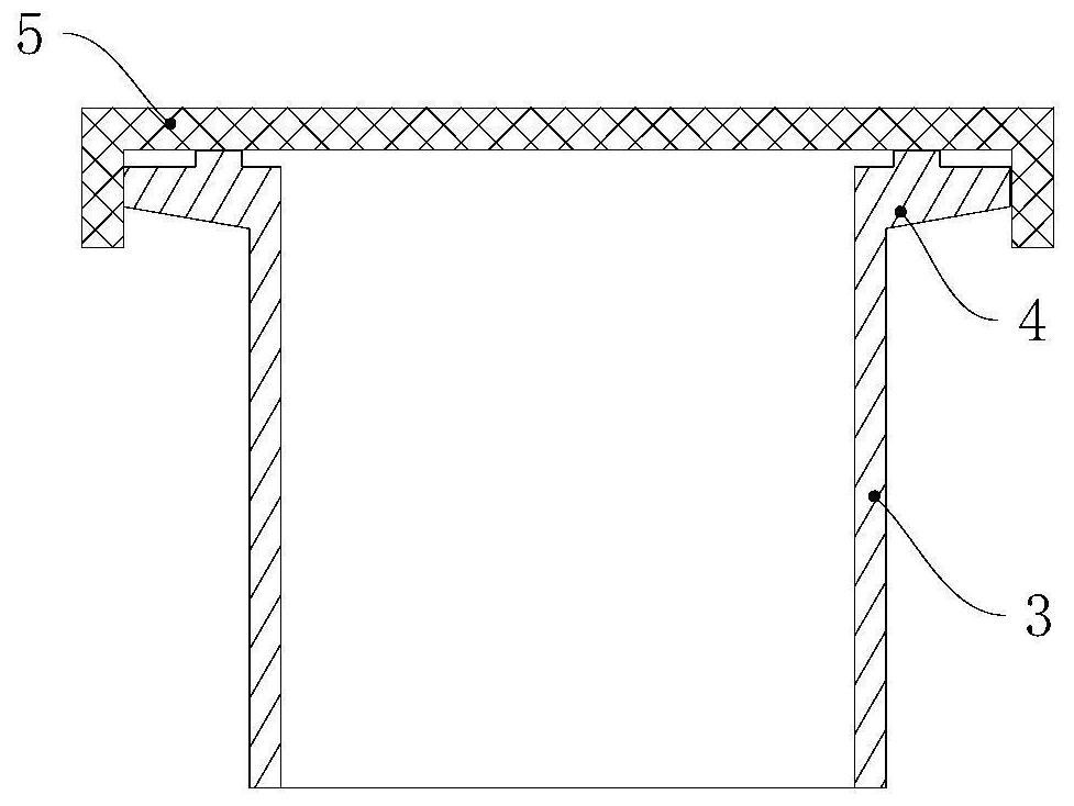
[0046] When the vent pipe joint 3 does not have the vent pipe joint flange 4, the blocking cover in this embodiment can be used. In this embodiment, the side wall 12 of the cover body 1 is coated on the outer wall of the vent pipe joint 3, and the cover body The bottom surface 11 of 1 is in contact with the end surface of the air pipe joint 3, and the side wall 12 of the cover body 1 can strengthen the overall fixing effect of the block, and because the side wall 12 of the cover body 1 is completely covered on the outer wall of the air pipe joint 3...
Embodiment 3
[0048] refer to Figure 7 The difference between this embodiment and Embodiment 1 and Embodiment 2 is that the longitudinal section of the side wall 12 of the cover body 1 in this embodiment is a planar structure arranged parallel to the outer wall of the vent pipe joint 3, and the side wall 12 Threads are provided near the inner surface of the vent pipe joint 3, and in this embodiment, the wall thickness of the plug body 2 is 6 mm, the length of the round platform 21 is 1 / 5 of the length of the plug body 2, and the number of positioning ribs 22 is 6 .
[0049] When the outer wall of the air pipe joint 3 is provided with threads, the side wall 12 of the cover body 1 can be provided with matching threads, and the side wall 12 of the cover body 1 and the outer wall of the air pipe joint 3 are connected by threads, and its installation and Disassembly is more convenient, and the fixing and sealing effects are further enhanced. The length of the round platform 21 and the number o...
PUM
 Abstract
Description
Claims
Application Information
 - R&D
- Intellectual Property
- Life Sciences
- Materials
- Tech Scout
- Unparalleled Data Quality
- Higher Quality Content
- 60% Fewer Hallucinations
Browse by: Latest US Patents, China's latest patents, Technical Efficacy Thesaurus, Application Domain, Technology Topic, Popular Technical Reports.
© 2025 PatSnap. All rights reserved.Legal|Privacy policy|Modern Slavery Act Transparency Statement|Sitemap|About US| Contact US: help@patsnap.com


