A ternary lithium battery intermittent packaging equipment
A ternary lithium battery, intermittent technology, applied in packaging and other directions, can solve the problems of mutual collision and extrusion, affecting the integrity and aesthetics of the ternary lithium battery, unfavorable sales, etc., to ensure the efficiency of packaging and the integrity. and aesthetics, reducing the effect of working procedures
- Summary
- Abstract
- Description
- Claims
- Application Information
AI Technical Summary
Problems solved by technology
Method used
Image
Examples
Embodiment 1
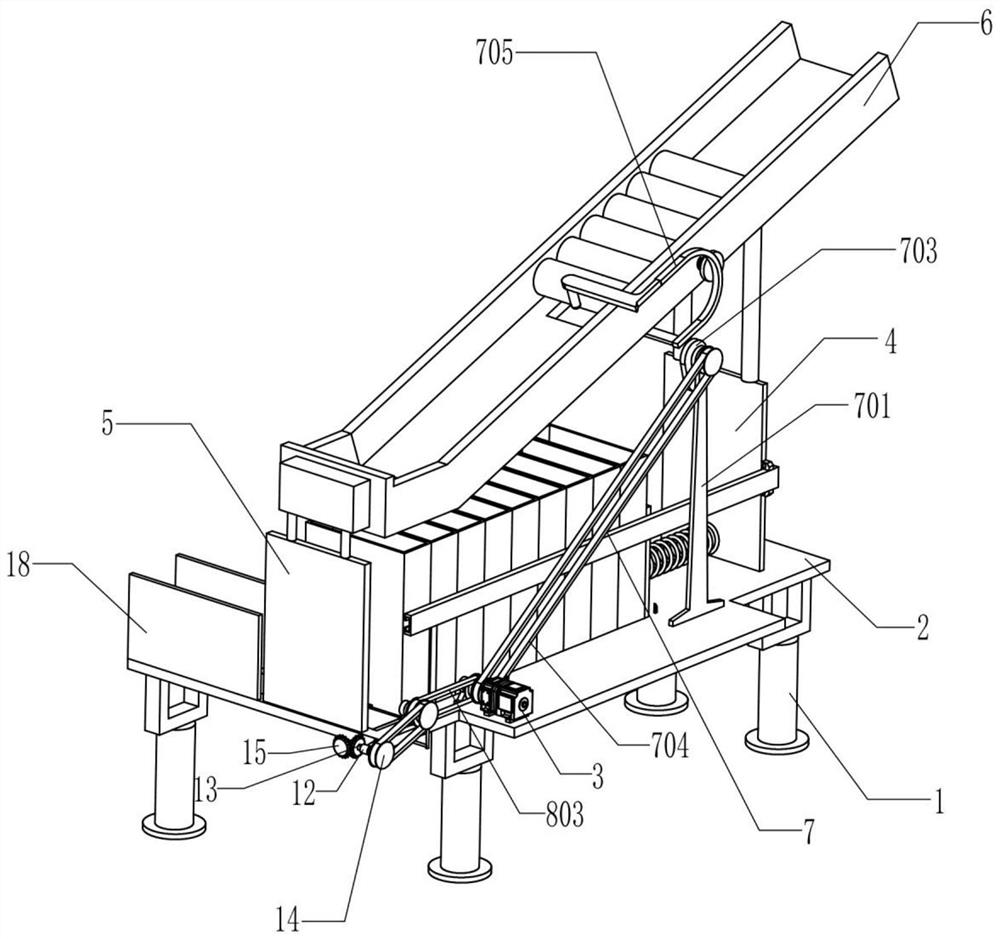
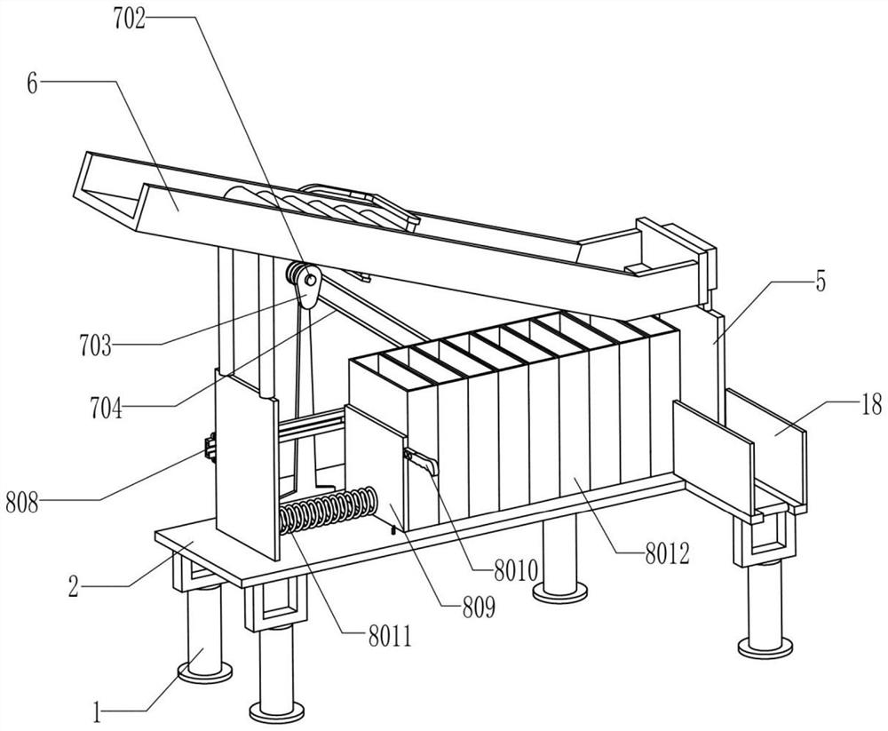
[0022] A ternary lithium battery intermittent packaging equipment, such as Figure 1-5 As shown, it includes a base 1, a mounting plate 2, a servo motor 3, a first support plate 4, a second support plate 5, a conveying frame 6, a lithium battery gap drop device 7 and a receiving frame replacement device 8, the four The base 1 is placed on the ground, the mounting plates 2 are fixedly mounted on the upper ends of the four bases 1, the servo motor 3 is fixedly mounted on the upper side of the left part of the mounting plate 2, and the first support plate 4 is fixedly mounted on the mounting plate 2. The upper side of the plate 2 is away from the servo motor 3, the second support plate 5 is fixedly installed on the upper side of the left part of the installation plate 2 and is opposite to the first support plate 4, the first support plate 4 and the second support A conveying frame 6 is installed between the plates 5, and the conveying frame 6 is set with a low left and a right hi...
Embodiment 2
[0025] On the basis of Example 1, as Figure 1-2 and Figure 4As shown, the lithium battery gap drop device 7 for controlling the intermittent drop of the ternary lithium battery in the transport frame 6 includes a mounting base 701, a first rotating shaft 702, a cam 703, a first transmission assembly 704, a swing frame 705, The first limiting rod 706, the second limiting rod 707 and the torsion spring 708, the mounting seat 701 is fixedly installed on the upper side of the mounting plate 2 and is close to the first support plate 4, and the first rotating shaft 702 is rotatably installed on the In the mounting seat 701 and through the mounting seat 701, the cam 703 is installed on the rear end of the first rotating shaft 702 and is located at the rear side of the mounting seat 701, between the front end of the first rotating shaft 702 and the output shaft of the servo motor 3 A first transmission assembly 704 is installed, the swing frame 705 is rotatably installed on the fro...
Embodiment 3
[0030] On the basis of Example 2, such as figure 1 and image 3 As shown, it also includes a first transmission roller 9, a second transmission roller 10, a conveyor belt 11, a second bearing seat 12, a transmission shaft 13, a third transmission assembly 14 and a bevel gear 15, and the first transmission roller 9 rotates mounted on the left part of the mounting plate 2, the second drive roller 10 is rotatably mounted on the left part of the mounting plate 2 and passes through the mounting plate 2, the first drive roller 9 and the second drive roller 10 are connected There is a conveyor belt 11, and the conveyor belt 11 is used to transport the disassembled lithium battery receiving frame 8012 to the side for collection without manual collection. The second bearing seat 12 is fixedly installed on the mounting plate 2, And close to the second support plate 5, the transmission shaft 13 is rotatably installed in the second bearing seat 12, the third transmission assembly 14 is i...
PUM
 Abstract
Description
Claims
Application Information
 - Generate Ideas
- Intellectual Property
- Life Sciences
- Materials
- Tech Scout
- Unparalleled Data Quality
- Higher Quality Content
- 60% Fewer Hallucinations
Browse by: Latest US Patents, China's latest patents, Technical Efficacy Thesaurus, Application Domain, Technology Topic, Popular Technical Reports.
© 2025 PatSnap. All rights reserved.Legal|Privacy policy|Modern Slavery Act Transparency Statement|Sitemap|About US| Contact US: help@patsnap.com


