Etching equipment and etching method

An etching equipment and technology to be etched, applied in the manufacture of discharge tubes, electrical components, semiconductor/solid-state devices, etc., can solve the problems of low etching uniformity, high power consumption, spare parts cost and large maintenance workload. , to achieve the effect of reducing unevenness, improving yield, saving spare parts cost and maintenance workload

Inactive Publication Date: 2020-09-15
SIEN QINGDAO INTEGRATED CIRCUITS CO LTD
View PDF0 Cites 1 Cited by
  • Summary
  • Abstract
  • Description
  • Claims
  • Application Information

AI Technical Summary

Problems solved by technology

[0005] In view of the above-mentioned shortcomings of the prior art, the object of the present invention is to provide an etching device and an etching method, which are used to solve the problem of low etching uniformity and low power consumption of the existing etching equipment and etching methods. High cost, spare parts cost and maintenance workload

Method used


Image

  • Etching equipment and etching method
  • Etching equipment and etching method
  • Etching equipment and etching method

Examples


Embodiment 1

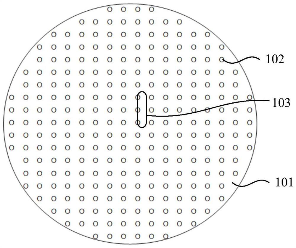
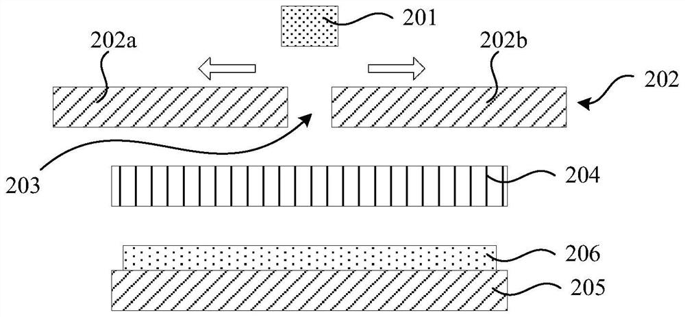
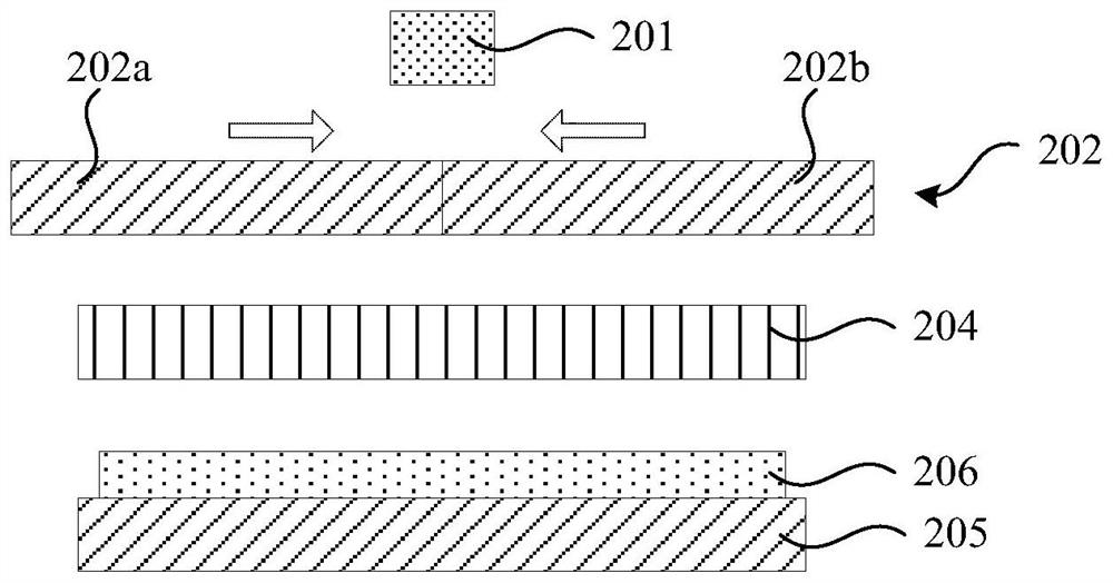
[0057] An etching device is provided in this embodiment, please refer to figure 2 and image 3 , is shown as a structural schematic diagram of the etching equipment, including a plasma generator 201, a flow plate 204, a shield assembly 202 and a wafer moving assembly 205, wherein the plasma generator is used to generate plasma to be etched The wafer 206 is etched; the uniform flow plate 204 is arranged below the plasma generator 201, and includes a body 204a and a plurality of through holes 204b for allowing the plasma to pass through the body 204a (see subsequent Figure 5 ); the baffle plate assembly 202 can be opened and closed between the plasma generator 201 and the even flow plate, wherein, when the baffle plate assembly 202 is closed (such as image 3 shown), the even flow plate 204 is completely covered under the baffle plate assembly 202, when the baffle plate assembly 202 is opened (as figure 2 As shown), a window 203 is formed to expose a part of the uniform flo...

Embodiment 2

[0070] An etching method is provided in this embodiment, please refer to Figure 7 , shown as a process flow diagram of the etching method, including the following steps:

[0071] S1: Open the baffle plate assembly to form a window to expose a part of the flow plate, so that the plasma generated by the plasma generator reaches the flow plate through the window;

[0072] S2: Use the wafer moving component to carry the wafer, and drive the wafer to move, so that the area to be etched of the wafer passes through the area below the part of the uniform flow plate exposed by the window, and is passed through the uniform flow plate plasma etching.

[0073] Specifically, the shading panel assembly adopts an openable and closable type. Such as figure 2 As shown, when the baffle plate assembly 202 is opened, a window 203 is formed to expose a part of the uniform flow plate 204, so as to allow the plasma to reach the uniform flow plate 204 through the window 203; image 3 As shown, ...


PUM


Abstract

The invention provides etching equipment and an etching method. The etching equipment comprises a plasma generator, a flow homogenization disc, a baffle assembly and a wafer moving assembly, wherein the baffle assembly is arranged between a plasma generator and the flow homogenization disc in an openable and closable manner, when the baffle assembly is opened, a window is formed to expose one partof the flow homogenization disc so as to allow plasma to reach the flow homogenization disc through the window, and the wafer moving assembly is arranged below the flow homogenization disc and is used for bearing a to-be-etched wafer and driving the to-be-etched wafer to move, so that the to-be-etched region of the wafer passes through a region below the part, exposed by the window, of the flow homogenization disc according to a preset path and is etched by plasmas passing through the flow homogenization disc. According to the invention, the etching uniformity can be improved, the spare partcost and the equipment maintenance workload can be reduced to a certain extent, and the radio frequency power consumption is reduced.

Description

technical field [0001] The invention belongs to the field of semiconductor integrated circuits, and relates to an etching device and an etching method. Background technique [0002] The electrostatic chucks (E-Chuck) of dry etching (Dry Etch) equipment commonly used in the market are all fixed, and the plasma (Plasma) adopts a uniform flow covering type. The shortcoming of the current design is that the plasma covers the entire area of ​​the wafer after passing through the uniform flow plate, resulting in inconsistent uniformity, resulting in poor uniformity of process results, and manufacturers in the industry cannot greatly improve the impact of this unevenness on products. Impact. [0003] The area of ​​the full-coverage plasma uniform flow plate is slightly larger than the wafer size, and the uniformity of the physical size of the holes is difficult to control. When the plasma is injected into the uniform flow plate, it is columnar, and the cross-sectional area is abou...

Claims


Application Information

Patent Timeline
Patent Type & Authority Applications(China)
IPC IPC(8): H01J37/20H01J37/30H01J37/305H01J37/32H01L21/67
CPCH01J37/20H01J37/3002H01J37/3056H01J37/32633H01J37/32752H01L21/67069
Inventor 朱本均
Owner SIEN QINGDAO INTEGRATED CIRCUITS CO LTD
Why Eureka
Try Eureka