Saw cutting end milling machine

An end milling and sawing technology, applied in metal processing machinery parts, clamping, supporting and other directions, can solve the problem of low efficiency of positioning operation and achieve the effect of improving construction efficiency

Pending Publication Date: 2020-09-15
仝红彬
View PDF0 Cites 4 Cited by
  • Summary
  • Abstract
  • Description
  • Claims
  • Application Information

AI Technical Summary

Problems solved by technology

[0003] The purpose of the present invention is to provide a sawing end milling machine, which solves the problem that the conventional sawing end milling machine cannot realize the low efficiency of assembly line operation during the normal use of positioning, cutting and end milling.

Method used


Image

  • Saw cutting end milling machine
  • Saw cutting end milling machine
  • Saw cutting end milling machine

Examples


Embodiment Construction

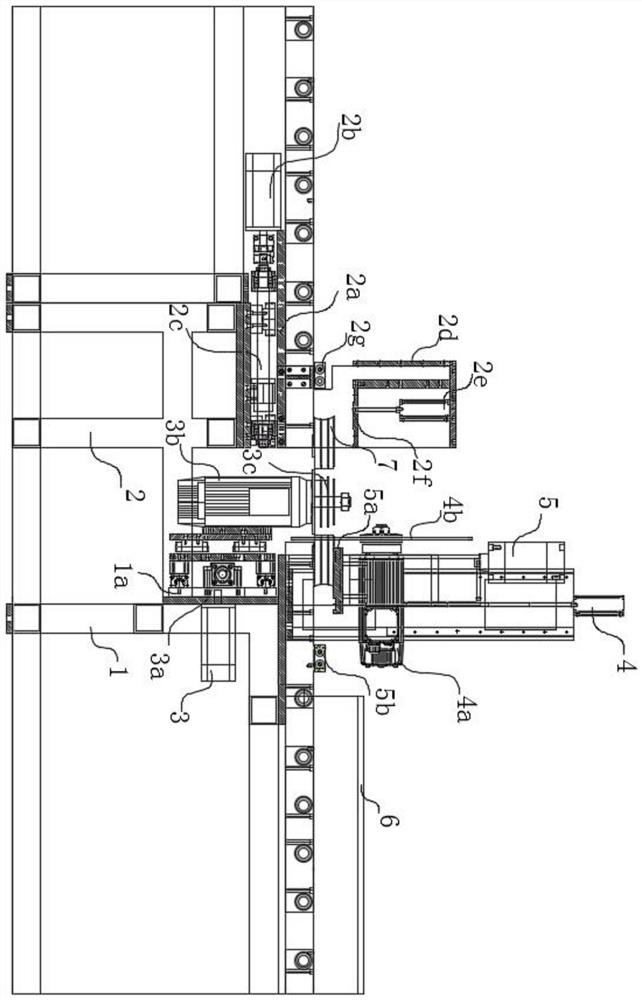
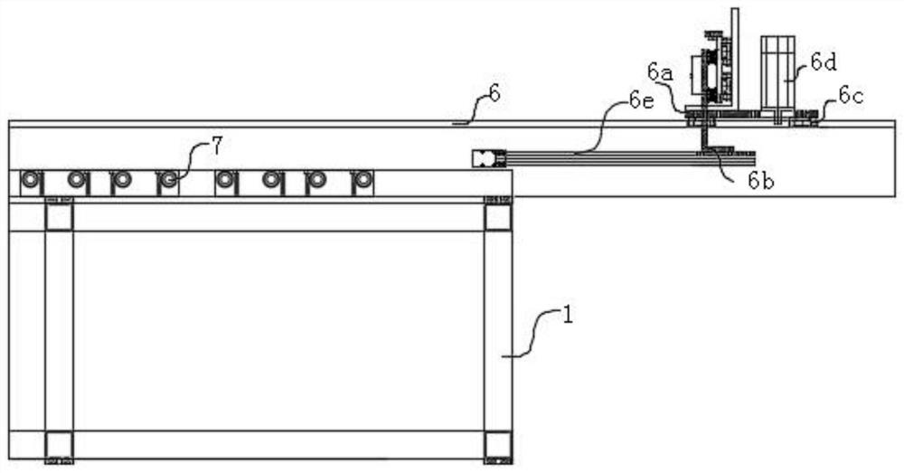
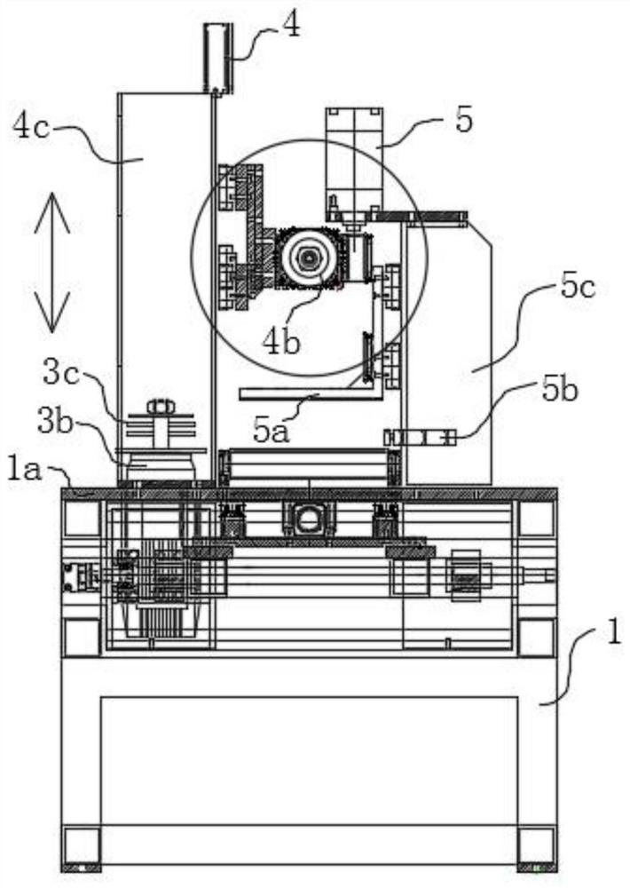
[0021] Such as Figure 1-5 As shown, a sawing end milling machine is disclosed in this embodiment, comprising a first conveying platform 1, a second conveying platform 2 installed at intervals in the same conveying direction as the first conveying platform 1, and a second conveying platform 2 installed on the first conveying platform 1 On the conveying platform 1, the 90-degree saw blade motor 4a, which cuts off the multiple profiles conveyed on the first conveying platform 1 and the second conveying platform 2, is installed on the first conveying platform 1 and in the horizontal direction The reciprocating motion carries out the milling cutter motor 3b that carries out horizontal end milling to the ends of a plurality of profiles cut off by the 90-degree saw blade motor 4a, and the feeding moving guide rail 6 installed on the first conveying platform 1 and the feeding moving guide rail 6 installed on the first conveying platform 1. The feeding manipulator 6e for conveying pro...


PUM


Abstract

The invention discloses a saw cutting end milling machine. A first conveying platform, a second conveying platform arranged in the same conveying direction of the first conveying platform in a spacedmanner, a 90-degree saw web motor and a milling tool motor are included, wherein the 90-degree saw web motor is arranged on the first conveying platform and cuts a plurality of side-by-side sectionalmaterials conveyed on the first conveying platform and the second conveying platform, the milling tool motor is arranged on the first conveying platform, reciprocates in the horizontal direction and conducts horizontal end milling on the end portions of the sectional materials cut by the 90-degree saw web motor. The conveying platforms are provided with transverse and longitudinal positioning mechanisms for positioning so that sectional material positioning can be achieved, a cutting motor is utilized for cutting, lifting is controlled, finally, a multi-layer milling tool disc is utilized formachining one-time forming of the sectional materials, a feeding mechanical arm on a feeding moving guide rail is utilized for rapid conveying and material preparing, assembly line type operation is achieved, and the construction efficiency is improved.

Description

technical field [0001] The invention relates to the technical field of aluminum alloy door and window processing, in particular to a sawing end milling machine. Background technique [0002] Conventionally, end milling is required for the processing of aluminum alloy doors and windows or other profiles, but due to manual operation of conventional end milling machines, the efficiency of manual operations in the process of positioning, sawing and subsequent end milling is low, and It is also easy to have the situation that the positioning is not accurate enough. In addition, in the entire assembly line production, the material cannot be fed and replenished in time, which also makes the work efficiency of the end milling machine lower. Contents of the invention [0003] The purpose of the present invention is to provide a sawing and end milling machine, which solves the problem that the conventional sawing and end milling machine cannot realize the low efficiency of assembly ...

Claims


Application Information

Patent Timeline
Patent Type & Authority Applications(China)
IPC IPC(8): B23P23/02B23Q3/06B23Q7/00
CPCB23P23/02B23Q3/062B23Q7/00
Inventor 仝红彬
Owner 仝红彬
Why Eureka
Try Eureka