Numerical control machine tool clamp for motor casing machining

A technology for CNC machine tools and motor casings, which is applied in the direction of chucks, etc., can solve the problems of high rejection rate of casings, deformation of casings, and difficulty in ensuring coaxiality, and achieve the effect of improving positioning firmness.

Active Publication Date: 2020-09-15
TAIZHOU BAIDA ELECTRICAL APPLIANCE CO LTD
View PDF8 Cites 2 Cited by
  • Summary
  • Abstract
  • Description
  • Claims
  • Application Information

AI Technical Summary

Problems solved by technology

[0004] For the above-mentioned three-grip chuck, in the process of clamping and fixing the casing, due to the small thickness of the casing, the extrusion of the claws on the casing will easily cause deformation of the casing, so the casing will It is difficult to ensure the coaxiality between it and the inner cavity of the casing, and the casing with too large deviation cannot be used and must be scrapped. Therefore, this clamping fixing method is easy to cause the machine Shell scrap rate is too high

Method used


Image

  • Numerical control machine tool clamp for motor casing machining

Examples


Embodiment Construction

[0026] The present invention will be described in further detail below in conjunction with the accompanying drawings.

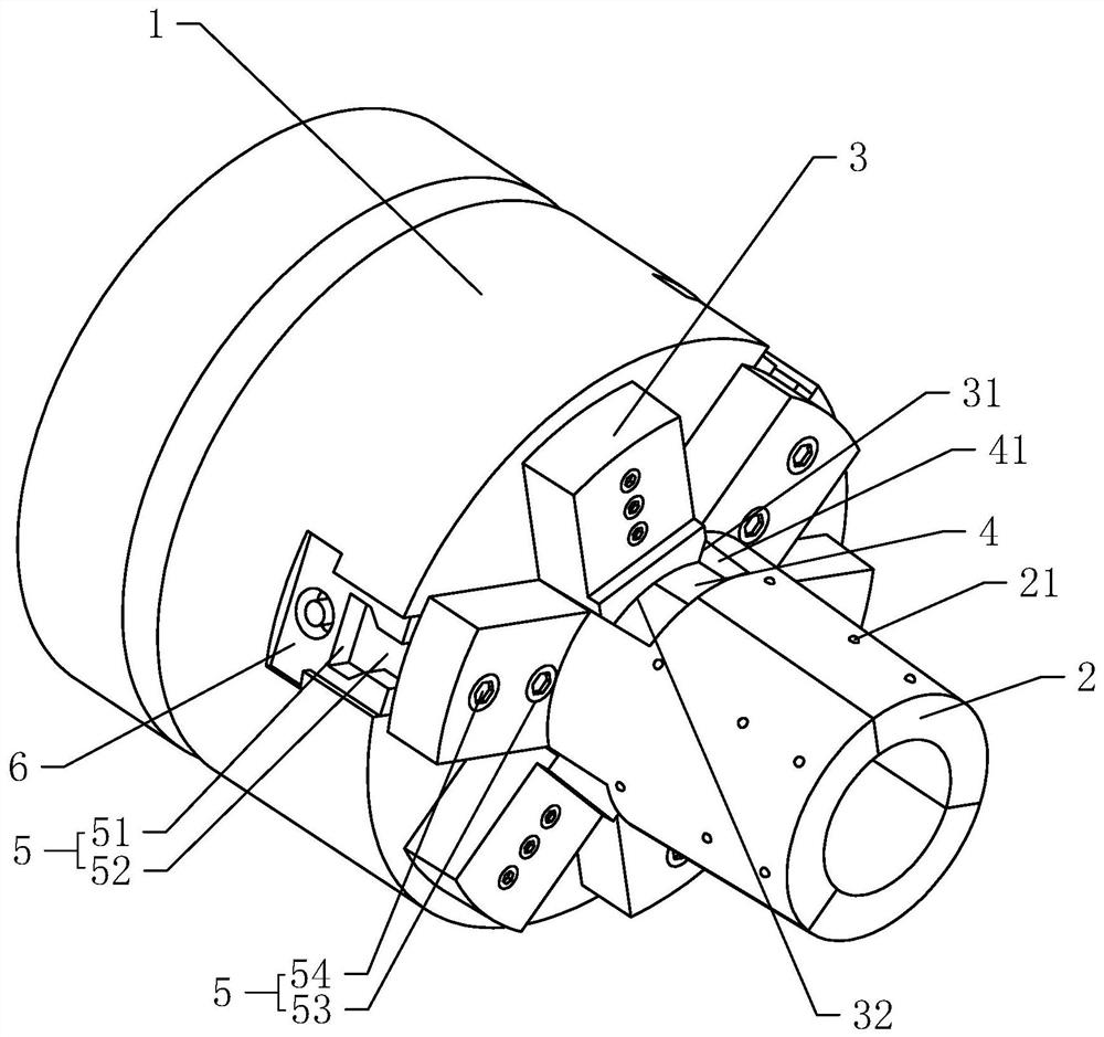
[0027] Such as figure 1 As shown, a CNC machine tool fixture for motor shell processing, including a hydraulic three-grip chuck 1, a centering support block 2, a centering block 3, and a positioning groove 4, and the hydraulic three-grab chuck 1 is fixed on the spindle of the CNC machine tool Above; the number of centering support blocks 2 is equal to the number of jaws 6 of the hydraulic three-grip chuck 1, fixed on the jaws 6 through the connection assembly 5, and the centering support blocks 2 are joined together to form a hollow centering column .

[0028] The diameter of the outer circle of the centering support block 2 gradually increases from the end away from the hydraulic three-grip chuck 1 towards the claw 6, so that the casing is set on the centering column formed by the centering support block 2. , when the centering support block 2 expands outw...


PUM


Abstract

The invention discloses a numerical control machine tool clamp for motor casing machining, and relates to clamps. The numerical control machine tool clamp is used for solving the problem that a motorcasing is prone to deform when being clamped by a common clamp. The numerical control machine tool clamp comprises a hydraulic three-jaw chuck arranged on a rack, and further comprises centering supporting blocks fixed on clamping jaws of the hydraulic three-jaw chuck, wherein the number of the centering supporting blocks is equal to that of the clamping jaws, and the plurality of centering supporting blocks are spliced to form a hollow centering column. The numerical control machine tool clamp for motor casing machining has the following advantages and effects that the centering supporting blocks in an inner supporting form can correct the motor casing in the motor casing supporting process, and deviation of the central axis in the motor casing in the positioning process is reduced so that the position of the central axis of the motor casing can be conveniently and accurately found in the subsequent tool setting process, the coaxiality between a shaft penetrating hole in the motor casing and an inner cavity of the motor casing is improved, and then the purpose of reducing the rejection rate of the motor casing is achieved.

Description

technical field [0001] The invention relates to a fixture, in particular to a numerically controlled machine tool fixture for machining motor casings. Background technique [0002] The motor is a very commonly used power component in the industry. One of the key factors determining its power conversion efficiency is the concentricity between the inner cavity of the motor and the through-shaft hole on the casing for the rotor to pass through. Therefore, when turning the through-shaft hole In the process, it is necessary to ensure its concentricity as much as possible, and the key to affecting this parameter lies in the clamping accuracy of the casing processing. Generally, the processing of the casing is carried out on the CNC machine tool, and the fixture is generally three-grip Chuck. [0003] At present, the Chinese invention with the authorized notification number CN206405449U discloses a high-efficiency three-grab chuck for machine tool processing, including a chuck bod...

Claims


Application Information

Patent Timeline
IPC IPC(8): B23B31/103B23B31/30
CPCB23B31/103B23B31/302
Inventor 张启斌邵伯明尤国金张明涛蒋奎林程峰周陈伟王强
Owner TAIZHOU BAIDA ELECTRICAL APPLIANCE CO LTD
Why Eureka
Try Eureka